ITM207 Chapter 4 Notes
Computers and Electricity
Gate:
A device that performs a basic operation on electrical signals
Circuits
Gates combined to perform more complicated tasks
We describe the behavior of gates and circuits through 3 ways
Boolean Expressions
● Uses Boolean algebra, a mathematical notation for expressing two-valued logic
Logic Diagrams
● A graphical representation of a circuit; each gates has it’s own symbol
Truth Tables
● A table showing all possible input values and the associated output values
Gates
6 Types of Gates:
● NOT
● AND
● OR
● XOR
● NAND
● NOR
Typically, logic diagrams are black with gates being told apart by their shape only
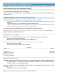
NOT Gate
A NOT gate accepts one input signal (0 or 1) and returns the opposite signal as output
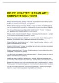
,AND Gate
An AND gate accepts two input signals
If both inputs are 1: output = 1
Otherwise input is 0
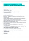
OR Gate
An OR gate accepts two input signals
If both inputs are 0: output = 0
Otherwise output is 1
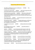
, XOR Gate
An XOR gate accepts two input signals
● If both inputs are the same output is 0
● Otherwise output is 1
● The difference between XOR gate and the OR gate is in one input situation
● (When both inputs are 1, the OR gate products a 1 and the XOR produces a 0)
● XOR output is 1 if (and only if):
● Either one input or the other is 1 and this is excluding the case that they both are
NAND Gate
The NAND (“NOT of AND”) gate accepts two input signals
● If both are 1, the output is 0
● Otherwise the output is 1
Computers and Electricity
Gate:
A device that performs a basic operation on electrical signals
Circuits
Gates combined to perform more complicated tasks
We describe the behavior of gates and circuits through 3 ways
Boolean Expressions
● Uses Boolean algebra, a mathematical notation for expressing two-valued logic
Logic Diagrams
● A graphical representation of a circuit; each gates has it’s own symbol
Truth Tables
● A table showing all possible input values and the associated output values
Gates
6 Types of Gates:
● NOT
● AND
● OR
● XOR
● NAND
● NOR
Typically, logic diagrams are black with gates being told apart by their shape only
NOT Gate
A NOT gate accepts one input signal (0 or 1) and returns the opposite signal as output
,AND Gate
An AND gate accepts two input signals
If both inputs are 1: output = 1
Otherwise input is 0
OR Gate
An OR gate accepts two input signals
If both inputs are 0: output = 0
Otherwise output is 1
, XOR Gate
An XOR gate accepts two input signals
● If both inputs are the same output is 0
● Otherwise output is 1
● The difference between XOR gate and the OR gate is in one input situation
● (When both inputs are 1, the OR gate products a 1 and the XOR produces a 0)
● XOR output is 1 if (and only if):
● Either one input or the other is 1 and this is excluding the case that they both are
NAND Gate
The NAND (“NOT of AND”) gate accepts two input signals
● If both are 1, the output is 0
● Otherwise the output is 1