Covers All Chapters
SOLUTIONS MANUAL
,Chapter 1 Solutions
P1.1 This example shows how the First Law can be applied to individual processes and how these can make
up a cycle.
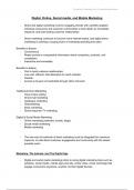
A cycle of events is shown in Fig A.10. It is made up of four processes, and the heat and work associated with
those processes is as given.
Fig A.10: Cycle of events made up of four processes.
Process 12: Q = +10J W = -18J
Process 23: Q = +100J W = 0J
Process 34: Q = -20J W = +70J
Process 41: Q = -10J W = +28J
Calculate the values of Un - U1, the net work, the net heat transfer and the heat supplied for the cycle.
Solution
This problem can be solved by applying the First Law to each of the processes in turn, when the change in
internal energy is dU Q W .
Process 1 2: dU12 U2 U1 Q12 W12 10 18 28J Process 2 3: dU23
U3 U2 Q23 W23 100 0 100J Process 3 4: dU34 U4 U3 Q34 W34
20 70 90J Process 4 1: dU41 U1 U4 Q41 W41 10 28 38J
The change in internal energy relative to the internal energy at point 1, U1, is given by
dU1n Un U1 Un Un 1 Un 1 Un 2 ......U2 U1
dUn 1,n dUn 2,n 1 ......dU12
Hence:
dU12 U 2 U1 28J
dU13 dU12 dU23 28 100 128J
dU14 dU12 dU23 dU34 28 100 ( 90) 38J
dU11 dU12 dU23 dU34 dU41 28 100 ( 90) ( 38) 0J
The result dU11 = 0 confirms that the four processes constitute a cycle, because the net change of state is zero.
The net work done in the cycle is
W W12 W23 W34 W41
cycle
18 0 70 28 80J
The positive sign indicates that the system does work on the surroundings. The net
heat supplied in the cycle is
Solutions Chapter 1 Page 1
D E Winterbone Current edition: 13/02/2015
,Chapter 1 Solutions
Q Q12 Q23 Q34 Q41
cycle
10 100 20 10 80J
Hence the net work done and net heat supplied are both 80J, as would be expected because the state of the
system has not changed between both ends of the cycle. It is also possible to differentiate between the heat
supplied to the system, Q > 0, and heat rejected from the system, Q < 0. In this case the total heat supplied is
Q Q12 Q23
cycle
10 100 110J
while the heat rejected is the sum of the negative heat transfer terms, viz.:
Q Q34 Q41
cycle .
20 10 30J
It should also be noted that the work done, W, is the difference between the heat supplied and that rejected.
This is an important point when considering the conversion of heat into work, which is dealt with by the Second
Law of Thermodynamics.
P1.2
There are two ways to solve this problem:
1. A simple one based on the p-V diagram
2. A more general one based on the p-V relationship
Work done = Area under lines.
Assuming a linear spring, then a linear (straight) line relationship joins the points.
1 105
Hence, Work done by spring = Area abca = Ws 0.5 4 100kJ
2 103
Work done by gas = Area adeca = Area abca + Area adbca
105
= 100 1.0 0.5 150kJ
103
More general method is to evaluate the work as W pdV .
First find the relationship for the spring. If linear pg1 kV1 k ,and pg 2 kV2 k
p p
k g2 g1 8bar/m , 3and k 7bar
Thus V2 V1
giving pg 8V 7.
Solutions Chapter 1 Page 2
D E Winterbone Current edition: 13/02/2015
,Chapter 1 Solutions
δWg pg dV , 2
giving W 2 2
8V 7 dV
8V 7V
g
Work done by gas,
1
2 1
2
4 2.25 1 7 1.5 1 10 150kJ
δWs psdV
2 2
Work done by spring, V2
Ws 8V 8 dV 8 V 100kJ
1
2 1
The benefit of the latter approach is that it can be applied in the case of a non-linear spring: it is more difficult to use the
simpler approach.
P1.3
p1 1.5
Pressure of gas is proportional to diameter, i.e. p d, giving p1 kd1, and hence k 5bar/m
13
d1 0.3
6V
d 3 , thus d
VolumeV 6
Work done during process, W pdV
3 d2 d2
Working in terms of d dV dd dd
2 6 k 2 2 k d
2 4 4
W kd d dd d 3.dd 2
d1
1
2 2 1 2 4 4
5 0.334 0.34 105 738J
4 2
This problem can also be solved in terms of V; however, it cannot be solved using a linear approximation. You might have
been close to the correct solution for P1.3, but it does not work for P1.4.
P1.4
The problem is the same as
2 P1.3, but the final2diameter is 1m.
2 k k d2 4 4
W kd d dd d 3.dd d1
The work done is 1
2 25 1 2 4 4
4 4
5 1.0 0.3 10 194759J
4 2
Using the WRONG APPROACH, assuming a linear relationship, gives
W
1.5 5
d 3 d 3 105 165580J
2 6 2 1
P1.5
ts at 20bar = 212.4 C
Initial conditions:
u 2600kJ / kg; h 2799kJ / kg; v 0.0995m3 / kg
g g g
p 20bar;t 500 C
Final conditions:
u 3116kJ / kg; h 3467kJ / kg; v 0.1756m3 / kg
g g g
To evaluate the energy added use 1st Law for closed system
Q dU W dU pdV
Solutions Chapter 1 Page 3
D E Winterbone Current edition: 13/02/2015
,Chapter 1 Solutions
Q m 3116 2600 20 105 0.1756 0.09957
103
Hence energy added,
3 516 152.06 2004kJ
Alternative method
Constant pressure process, hence enthalpy can be used
Q dh m h2 h1 3 3467 2799 2004kJ
5
20 10 0.1756 0.9957 3 456kJ
W 103
P1.6
This is a constant3 volume (isochoric) process. Hence
v 0.00317m /kg at critical point, and v 0.00317m3 /kg.
1 1
But v2 xvg 1 x v f v f xvfg
At p2 27.5bar, interpolation v g 0.072788m3 /kg, and t 2 229 C
3
Using the saturated water tables, vf = 0.001209m /kg
0.00317 0.001209
Hence, x 0.0274 2.74%
0.072788 0.001209
P1.7
Initial and final conditions:
p1A 3.5bar; m1A 1.0kg; x1A 1.0;ug1A 2549kJ / kg;u1A 2549kJ / kg
p1B 7.0bar; m1B 2.0kg; x1B 0.8;ug1B 2573kJ / kg;u f 1B 696kJ / kg;u1B 2197.6kJ / kg p2 5bar; m2
3.0kg
Total U1 2549 4395.2 6944.2kJ / kg
Volumes
vg1A 0.5241m33 / kg;V 1A 0.5241m3 / kg
0.2728m / kg; v 0.1107 10 2 m3 / kg(interp); V 0.21846m3 / kg
v g1B f 1B 1B
Total volume, V1 0.5241 2 0.21846 0.9610m3 / kg
Conditions at 2 3 3
V 0.9610m ; v V2 0.3203m / kg
2 2
m2
At 5bar, v 0.3748m3 / kg; v 01093 10 2 m3 / kg
g
v2 v f 2 0.3192 f
0.8541
x2 vg 2 v f 2 0.3737
Thus U 2 3 0.8541 2562 0.1459 639 6846kJ
Total heat transfer, Q U 2 U 1 98kJ
P1.8
Solutions Chapter 1 Page 4
D E Winterbone Current edition: 13/02/2015
,Chapter 1 Solutions
m 5kg; p1 14bar; x1 0.8
vg1 0.1408m3 / kg; v f 1 0.001149m3 / kg
ug1 2593kJ / kg;u f 1 828kJ / kg
v xv 1x v 0.1129m3 / kg :V 5 0.1129 0.5645m3
1 1 g1 1 f1 1
u1 x1ug1 1 x1 u f 1 2240kJ / kg :U1 5 2240 11200kJ
Spring equation, p = kV, because p = 0 when V = 0.
When volume is 150% of initial value, p 1.5 p 21bar :V 1.5 0.5645 0.8468m3
2 1 2
Work done, W p V kVdV
Hence, W pdV kVdV p1 p V2 V2 p1V1
VdV
V1 5
2V1 2
1
1 2
1.25
14 0.5645 10
1.25
3
494kJ 2
10
Conditions at 2: V 0.8468m3;v 0.16936m3 / kg : p 21bar
2 2 2
Based on steam tables condition 2 is in the superheat region: volumes listed below
p = 20bar 0.1634 0.1756
p = 21bar 0.1578 0.1696 (interpolated)
p = 30bar 0.1078 0.1161
Hence t2 = 500C
u2 3116 0.1 3108 3116 3115kJ / kg
U 2 5 3115 15576kJ
Thus
Heat transfer from 1st Law
Q dU W 15576 11200 494 4870kJ
P1.9
tA 20 C; ps 5.673bar; hg 195.78kJ / kg; hf 54.87kJ / kg
Tank A: 1kg Freon-12
105
ug hg pgv g 195.78 5.673 3
0.0308 178.3kJ / kg
10
Cylinder: isobaric expansion at 2bar
Heat transferred so temperature constant at 20°C:3 calculate heat transfer.
Flow across valve is isenthalpic: Vp1 0m ;V p2 ?
Initial energy, U 178.3kJ ; initial volume, V 0.0308m3
Final volume, V2 0.0969m3
1 1
5
2 10
0.0969 0.0308 13.22kJ
Hence work done, W pdV
103
Final energy, U 2 202.27 2 105 0.0969 182.9kJ
103
Hence, heat transfer, Q dU W 182.9 178.3 13.22 17.8kJ
Solutions Chapter 1 Page 5
D E Winterbone Current edition: 13/02/2015
,Chapter 1 Solutions
Problems P1.10 to P1.14 require the USFEE
These examples demonstrate that it is possible to obtain solutions for problems that have flows across the
system boundaries by closed system methods.
P1.10
An insulated bottle is initially evacuated, i.e. it contains a vacuum, and then the stopper is removed allowing
atmospheric air to fill the bottle. Evaluate the final conditions in a bottle when the air has just filled it.
Comment: This is a relatively complex problem in unsteady gas dynamics if the processes between the removal of
the stopper and the quiescent end state are considered in detail. In the flow processes pressure waves will
travel into the bottle and be reflected; these will cause the atmospheric air to start flowing into the bottle. The
waves will ultimately die out due to the flow interactions at the neck of the bottle and fluid friction, and finally a
steady state will be reached. The great strength of the approaches of thermodynamics are that they allow the
final state to be evaluated without any knowledge of gas dynamics.
The bottle is shown in Fig A. 11; it has a volume of V. At t = 0, referred to as state 1, there is no gas in the bottle
and its pressure is zero. Hence, p1 = 0 and m1 = 0. Gas is admitted to the bottle until the pressure of the gas
in the bottle is atmospheric pressure; p2 = patm. It is possible to treat this as a closed system problem if the
system boundaries are drawn in such a way that no flow occurs across them during the filling process. This
has been done by drawing a boundary around the gas which flows into the bottle during the process: in this case
it could be an actual boundary such as an extremely flexible balloon which has been filled sufficiently to hold all
the air required to fill the bottle.
Fig A.11: Bottle being filled with atmospheric air. The
bottle is initially evacuated: ma = 0 at t = 0.
Considering the total system at time t = 0, i.e. system a + system b. The First Law can be applied to the combined
system, giving
Q dU W .
In this case Q = 0, because the bottle is insulated. The total work done during the time interval is the pdV work
done on the gas in system b, because system a does not change volume and no stirring work is done. Hence
dU U2 U1 W ,
where U1 U1a U1b 0 minuin minuin
and U2 U2a U2b minu2 0 minu2.
Rearranging the equation gives
U2 U1 W
where W patmVin min patmvin .
Solutions Chapter 1 Page 6
D E Winterbone Current edition: 13/02/2015
,Chapter 1 Solutions
Thus U2 minu2 minu1 min patmvin min uin patmvin ,
giving the surprising result that the specific internal energy of the gas in the bottle is not the same as that of the
atmosphere, but is
u2 uin patmvin hin .
i.e. the internal energy of the gas in the bottle is equal to the enthalpy of the gas that was forced into the bottle. The
reason for this is that the atmosphere did work on pushing the gas from system b into system a.
P1.11 Filling a bottle which already contains some fluid.
The analysis adopted above may be applied to a bottle which is not initially evacuated, i.e. pa1 0.
This is shown in Fig P1.11. The approach to solving this problem is similar to that adopted above. The same
technique is used to make the problem a closed system one.
As before, Q = 0, because the bottle is insulated. The total work done during the time interval is the pdV work
done on the gas in system b, because system a does not change volume and no stirring work is done. The mass
of air in the bottle at the beginning of the process will be denoted by m1, and its specific internal energy will be
u1. Hence, again
dU U2 U1 W ,
but now U1 U1a U1b m1u1 minuin
and U2 U2a U2b minu2 0 minu2.
Fig P1.11(a): Filling of a bottle which is not initially evacuated
Rearranging the equation gives
U2 U1 W
where W patmVin min patmvin .
Thus U 2 minu2 m1u1 minuin min patmvin m1u1 min uin patmvin ,
where min m2 m1. Substituting this value in the equation for u2 gives
min uin pinvin minhin m2 m1 hin m2u2 m1u1
which can be rearranged to give
m2 hin u2 m1 hin u1 .
This equation has two unknowns, m2 and u2, and, in general, has to be solved iteratively, i.e. by trial
and error. In the special case of a perfect gas, where pv RT, with cv R and cp R , it is
possible to get the following solution. 1 1
Solutions Chapter 1 Page 7
D E Winterbone Current edition: 13/02/2015
,Chapter 1 Solutions
Using the equation m2 hin u2 m1 hin u1
and substituting the following values for the initial and final conditions
u c T RT p1V1
1 m ,
1 v 1 ,
1 1
RT1
RT2 p2V2
u2 cvT2 , m2
1 RT2
and the value for the inflowing enthalpy
hin RT
a
1
gives
paV1 RTa RT2 p1V1 RTa RT1
.
RT1 1 RT1 1 1
1
This equation can be rearranged to give
T2 Ta
p1 Ta 1 1
pa T1
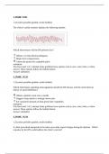
If p1 = 0, then the result reduces to that for filling an evacuated bottle, viz., T2 = Ta. Fig P1.11(b) shows how
the value of T2 varies with the ratios p1/pa and Ta/T1.
1.4
1.2
Temperature ratio, T 2/T a
1
T1/Ta=1.0
0.8 T1/Ta=0.8
T1/Ta=1.2
0.6
0 0.1 0.2 0.3 0.4 0.5 0.6 0.7 0.8 0.9 1
Pressure ratio, p 1/p a
Fig P1.11(b): Variation of temperature ratio, T2/Ta, with pressure ratio, p1/pa, for different levels of temperature
ratio, T1/Ta.
In the case of gases which are not perfect it is not possible to derive a simple equation for the variation of the
final temperature with initial conditions, and an iteration must be performed to evaluate it.
P1.12 Discharge from a bottle
The two questions above have dealt with filling a bottle, and shown how this can be considered to be a closed
system problem. A similar approach can be applied to a bottle discharging to the surroundings.
The system is shown in Fig P1.12.
Solutions Chapter 1 Page 8
D E Winterbone Current edition: 13/02/2015
, Chapter 1 Solutions
THOSE WERE PREVIEW PAGES
TO DOWNLOAD THE FULL PDF
CLICK ON THE L.I.N.K
ON THE NEXT PAGE
Solutions Chapter 1 Page 9
D E Winterbone Current edition: 13/02/2015
SOLUTIONS MANUAL
,Chapter 1 Solutions
P1.1 This example shows how the First Law can be applied to individual processes and how these can make
up a cycle.
A cycle of events is shown in Fig A.10. It is made up of four processes, and the heat and work associated with
those processes is as given.
Fig A.10: Cycle of events made up of four processes.
Process 12: Q = +10J W = -18J
Process 23: Q = +100J W = 0J
Process 34: Q = -20J W = +70J
Process 41: Q = -10J W = +28J
Calculate the values of Un - U1, the net work, the net heat transfer and the heat supplied for the cycle.
Solution
This problem can be solved by applying the First Law to each of the processes in turn, when the change in
internal energy is dU Q W .
Process 1 2: dU12 U2 U1 Q12 W12 10 18 28J Process 2 3: dU23
U3 U2 Q23 W23 100 0 100J Process 3 4: dU34 U4 U3 Q34 W34
20 70 90J Process 4 1: dU41 U1 U4 Q41 W41 10 28 38J
The change in internal energy relative to the internal energy at point 1, U1, is given by
dU1n Un U1 Un Un 1 Un 1 Un 2 ......U2 U1
dUn 1,n dUn 2,n 1 ......dU12
Hence:
dU12 U 2 U1 28J
dU13 dU12 dU23 28 100 128J
dU14 dU12 dU23 dU34 28 100 ( 90) 38J
dU11 dU12 dU23 dU34 dU41 28 100 ( 90) ( 38) 0J
The result dU11 = 0 confirms that the four processes constitute a cycle, because the net change of state is zero.
The net work done in the cycle is
W W12 W23 W34 W41
cycle
18 0 70 28 80J
The positive sign indicates that the system does work on the surroundings. The net
heat supplied in the cycle is
Solutions Chapter 1 Page 1
D E Winterbone Current edition: 13/02/2015
,Chapter 1 Solutions
Q Q12 Q23 Q34 Q41
cycle
10 100 20 10 80J
Hence the net work done and net heat supplied are both 80J, as would be expected because the state of the
system has not changed between both ends of the cycle. It is also possible to differentiate between the heat
supplied to the system, Q > 0, and heat rejected from the system, Q < 0. In this case the total heat supplied is
Q Q12 Q23
cycle
10 100 110J
while the heat rejected is the sum of the negative heat transfer terms, viz.:
Q Q34 Q41
cycle .
20 10 30J
It should also be noted that the work done, W, is the difference between the heat supplied and that rejected.
This is an important point when considering the conversion of heat into work, which is dealt with by the Second
Law of Thermodynamics.
P1.2
There are two ways to solve this problem:
1. A simple one based on the p-V diagram
2. A more general one based on the p-V relationship
Work done = Area under lines.
Assuming a linear spring, then a linear (straight) line relationship joins the points.
1 105
Hence, Work done by spring = Area abca = Ws 0.5 4 100kJ
2 103
Work done by gas = Area adeca = Area abca + Area adbca
105
= 100 1.0 0.5 150kJ
103
More general method is to evaluate the work as W pdV .
First find the relationship for the spring. If linear pg1 kV1 k ,and pg 2 kV2 k
p p
k g2 g1 8bar/m , 3and k 7bar
Thus V2 V1
giving pg 8V 7.
Solutions Chapter 1 Page 2
D E Winterbone Current edition: 13/02/2015
,Chapter 1 Solutions
δWg pg dV , 2
giving W 2 2
8V 7 dV
8V 7V
g
Work done by gas,
1
2 1
2
4 2.25 1 7 1.5 1 10 150kJ
δWs psdV
2 2
Work done by spring, V2
Ws 8V 8 dV 8 V 100kJ
1
2 1
The benefit of the latter approach is that it can be applied in the case of a non-linear spring: it is more difficult to use the
simpler approach.
P1.3
p1 1.5
Pressure of gas is proportional to diameter, i.e. p d, giving p1 kd1, and hence k 5bar/m
13
d1 0.3
6V
d 3 , thus d
VolumeV 6
Work done during process, W pdV
3 d2 d2
Working in terms of d dV dd dd
2 6 k 2 2 k d
2 4 4
W kd d dd d 3.dd 2
d1
1
2 2 1 2 4 4
5 0.334 0.34 105 738J
4 2
This problem can also be solved in terms of V; however, it cannot be solved using a linear approximation. You might have
been close to the correct solution for P1.3, but it does not work for P1.4.
P1.4
The problem is the same as
2 P1.3, but the final2diameter is 1m.
2 k k d2 4 4
W kd d dd d 3.dd d1
The work done is 1
2 25 1 2 4 4
4 4
5 1.0 0.3 10 194759J
4 2
Using the WRONG APPROACH, assuming a linear relationship, gives
W
1.5 5
d 3 d 3 105 165580J
2 6 2 1
P1.5
ts at 20bar = 212.4 C
Initial conditions:
u 2600kJ / kg; h 2799kJ / kg; v 0.0995m3 / kg
g g g
p 20bar;t 500 C
Final conditions:
u 3116kJ / kg; h 3467kJ / kg; v 0.1756m3 / kg
g g g
To evaluate the energy added use 1st Law for closed system
Q dU W dU pdV
Solutions Chapter 1 Page 3
D E Winterbone Current edition: 13/02/2015
,Chapter 1 Solutions
Q m 3116 2600 20 105 0.1756 0.09957
103
Hence energy added,
3 516 152.06 2004kJ
Alternative method
Constant pressure process, hence enthalpy can be used
Q dh m h2 h1 3 3467 2799 2004kJ
5
20 10 0.1756 0.9957 3 456kJ
W 103
P1.6
This is a constant3 volume (isochoric) process. Hence
v 0.00317m /kg at critical point, and v 0.00317m3 /kg.
1 1
But v2 xvg 1 x v f v f xvfg
At p2 27.5bar, interpolation v g 0.072788m3 /kg, and t 2 229 C
3
Using the saturated water tables, vf = 0.001209m /kg
0.00317 0.001209
Hence, x 0.0274 2.74%
0.072788 0.001209
P1.7
Initial and final conditions:
p1A 3.5bar; m1A 1.0kg; x1A 1.0;ug1A 2549kJ / kg;u1A 2549kJ / kg
p1B 7.0bar; m1B 2.0kg; x1B 0.8;ug1B 2573kJ / kg;u f 1B 696kJ / kg;u1B 2197.6kJ / kg p2 5bar; m2
3.0kg
Total U1 2549 4395.2 6944.2kJ / kg
Volumes
vg1A 0.5241m33 / kg;V 1A 0.5241m3 / kg
0.2728m / kg; v 0.1107 10 2 m3 / kg(interp); V 0.21846m3 / kg
v g1B f 1B 1B
Total volume, V1 0.5241 2 0.21846 0.9610m3 / kg
Conditions at 2 3 3
V 0.9610m ; v V2 0.3203m / kg
2 2
m2
At 5bar, v 0.3748m3 / kg; v 01093 10 2 m3 / kg
g
v2 v f 2 0.3192 f
0.8541
x2 vg 2 v f 2 0.3737
Thus U 2 3 0.8541 2562 0.1459 639 6846kJ
Total heat transfer, Q U 2 U 1 98kJ
P1.8
Solutions Chapter 1 Page 4
D E Winterbone Current edition: 13/02/2015
,Chapter 1 Solutions
m 5kg; p1 14bar; x1 0.8
vg1 0.1408m3 / kg; v f 1 0.001149m3 / kg
ug1 2593kJ / kg;u f 1 828kJ / kg
v xv 1x v 0.1129m3 / kg :V 5 0.1129 0.5645m3
1 1 g1 1 f1 1
u1 x1ug1 1 x1 u f 1 2240kJ / kg :U1 5 2240 11200kJ
Spring equation, p = kV, because p = 0 when V = 0.
When volume is 150% of initial value, p 1.5 p 21bar :V 1.5 0.5645 0.8468m3
2 1 2
Work done, W p V kVdV
Hence, W pdV kVdV p1 p V2 V2 p1V1
VdV
V1 5
2V1 2
1
1 2
1.25
14 0.5645 10
1.25
3
494kJ 2
10
Conditions at 2: V 0.8468m3;v 0.16936m3 / kg : p 21bar
2 2 2
Based on steam tables condition 2 is in the superheat region: volumes listed below
p = 20bar 0.1634 0.1756
p = 21bar 0.1578 0.1696 (interpolated)
p = 30bar 0.1078 0.1161
Hence t2 = 500C
u2 3116 0.1 3108 3116 3115kJ / kg
U 2 5 3115 15576kJ
Thus
Heat transfer from 1st Law
Q dU W 15576 11200 494 4870kJ
P1.9
tA 20 C; ps 5.673bar; hg 195.78kJ / kg; hf 54.87kJ / kg
Tank A: 1kg Freon-12
105
ug hg pgv g 195.78 5.673 3
0.0308 178.3kJ / kg
10
Cylinder: isobaric expansion at 2bar
Heat transferred so temperature constant at 20°C:3 calculate heat transfer.
Flow across valve is isenthalpic: Vp1 0m ;V p2 ?
Initial energy, U 178.3kJ ; initial volume, V 0.0308m3
Final volume, V2 0.0969m3
1 1
5
2 10
0.0969 0.0308 13.22kJ
Hence work done, W pdV
103
Final energy, U 2 202.27 2 105 0.0969 182.9kJ
103
Hence, heat transfer, Q dU W 182.9 178.3 13.22 17.8kJ
Solutions Chapter 1 Page 5
D E Winterbone Current edition: 13/02/2015
,Chapter 1 Solutions
Problems P1.10 to P1.14 require the USFEE
These examples demonstrate that it is possible to obtain solutions for problems that have flows across the
system boundaries by closed system methods.
P1.10
An insulated bottle is initially evacuated, i.e. it contains a vacuum, and then the stopper is removed allowing
atmospheric air to fill the bottle. Evaluate the final conditions in a bottle when the air has just filled it.
Comment: This is a relatively complex problem in unsteady gas dynamics if the processes between the removal of
the stopper and the quiescent end state are considered in detail. In the flow processes pressure waves will
travel into the bottle and be reflected; these will cause the atmospheric air to start flowing into the bottle. The
waves will ultimately die out due to the flow interactions at the neck of the bottle and fluid friction, and finally a
steady state will be reached. The great strength of the approaches of thermodynamics are that they allow the
final state to be evaluated without any knowledge of gas dynamics.
The bottle is shown in Fig A. 11; it has a volume of V. At t = 0, referred to as state 1, there is no gas in the bottle
and its pressure is zero. Hence, p1 = 0 and m1 = 0. Gas is admitted to the bottle until the pressure of the gas
in the bottle is atmospheric pressure; p2 = patm. It is possible to treat this as a closed system problem if the
system boundaries are drawn in such a way that no flow occurs across them during the filling process. This
has been done by drawing a boundary around the gas which flows into the bottle during the process: in this case
it could be an actual boundary such as an extremely flexible balloon which has been filled sufficiently to hold all
the air required to fill the bottle.
Fig A.11: Bottle being filled with atmospheric air. The
bottle is initially evacuated: ma = 0 at t = 0.
Considering the total system at time t = 0, i.e. system a + system b. The First Law can be applied to the combined
system, giving
Q dU W .
In this case Q = 0, because the bottle is insulated. The total work done during the time interval is the pdV work
done on the gas in system b, because system a does not change volume and no stirring work is done. Hence
dU U2 U1 W ,
where U1 U1a U1b 0 minuin minuin
and U2 U2a U2b minu2 0 minu2.
Rearranging the equation gives
U2 U1 W
where W patmVin min patmvin .
Solutions Chapter 1 Page 6
D E Winterbone Current edition: 13/02/2015
,Chapter 1 Solutions
Thus U2 minu2 minu1 min patmvin min uin patmvin ,
giving the surprising result that the specific internal energy of the gas in the bottle is not the same as that of the
atmosphere, but is
u2 uin patmvin hin .
i.e. the internal energy of the gas in the bottle is equal to the enthalpy of the gas that was forced into the bottle. The
reason for this is that the atmosphere did work on pushing the gas from system b into system a.
P1.11 Filling a bottle which already contains some fluid.
The analysis adopted above may be applied to a bottle which is not initially evacuated, i.e. pa1 0.
This is shown in Fig P1.11. The approach to solving this problem is similar to that adopted above. The same
technique is used to make the problem a closed system one.
As before, Q = 0, because the bottle is insulated. The total work done during the time interval is the pdV work
done on the gas in system b, because system a does not change volume and no stirring work is done. The mass
of air in the bottle at the beginning of the process will be denoted by m1, and its specific internal energy will be
u1. Hence, again
dU U2 U1 W ,
but now U1 U1a U1b m1u1 minuin
and U2 U2a U2b minu2 0 minu2.
Fig P1.11(a): Filling of a bottle which is not initially evacuated
Rearranging the equation gives
U2 U1 W
where W patmVin min patmvin .
Thus U 2 minu2 m1u1 minuin min patmvin m1u1 min uin patmvin ,
where min m2 m1. Substituting this value in the equation for u2 gives
min uin pinvin minhin m2 m1 hin m2u2 m1u1
which can be rearranged to give
m2 hin u2 m1 hin u1 .
This equation has two unknowns, m2 and u2, and, in general, has to be solved iteratively, i.e. by trial
and error. In the special case of a perfect gas, where pv RT, with cv R and cp R , it is
possible to get the following solution. 1 1
Solutions Chapter 1 Page 7
D E Winterbone Current edition: 13/02/2015
,Chapter 1 Solutions
Using the equation m2 hin u2 m1 hin u1
and substituting the following values for the initial and final conditions
u c T RT p1V1
1 m ,
1 v 1 ,
1 1
RT1
RT2 p2V2
u2 cvT2 , m2
1 RT2
and the value for the inflowing enthalpy
hin RT
a
1
gives
paV1 RTa RT2 p1V1 RTa RT1
.
RT1 1 RT1 1 1
1
This equation can be rearranged to give
T2 Ta
p1 Ta 1 1
pa T1
If p1 = 0, then the result reduces to that for filling an evacuated bottle, viz., T2 = Ta. Fig P1.11(b) shows how
the value of T2 varies with the ratios p1/pa and Ta/T1.
1.4
1.2
Temperature ratio, T 2/T a
1
T1/Ta=1.0
0.8 T1/Ta=0.8
T1/Ta=1.2
0.6
0 0.1 0.2 0.3 0.4 0.5 0.6 0.7 0.8 0.9 1
Pressure ratio, p 1/p a
Fig P1.11(b): Variation of temperature ratio, T2/Ta, with pressure ratio, p1/pa, for different levels of temperature
ratio, T1/Ta.
In the case of gases which are not perfect it is not possible to derive a simple equation for the variation of the
final temperature with initial conditions, and an iteration must be performed to evaluate it.
P1.12 Discharge from a bottle
The two questions above have dealt with filling a bottle, and shown how this can be considered to be a closed
system problem. A similar approach can be applied to a bottle discharging to the surroundings.
The system is shown in Fig P1.12.
Solutions Chapter 1 Page 8
D E Winterbone Current edition: 13/02/2015
, Chapter 1 Solutions
THOSE WERE PREVIEW PAGES
TO DOWNLOAD THE FULL PDF
CLICK ON THE L.I.N.K
ON THE NEXT PAGE
Solutions Chapter 1 Page 9
D E Winterbone Current edition: 13/02/2015