1
Electrical Circuits
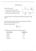
An RLC circuit consists of: 𝐸
A resistor with a resistance of R ohms
An inductor with an inductance of L henries
A capacitor with a capacitance of C farads
We assume that there is a source (a battery or generator) that supplies a voltage
of 𝐸(𝑡).
If the circuit is closed, a current of 𝐼(𝑡) amperes is generated and a charge of
𝑄(𝑡) coulombs on the capacitor at time 𝑡.
We have the following relation:
𝑑𝑄
= 𝐼 (𝑡).
𝑑𝑡
The voltage drop across the three circuit elements is given by:
Circuit Element Voltage Drop
𝑑𝐼
Inductor 𝐿
𝑑𝑡
Resistor 𝑅𝐼
1
Capacitor 𝑄
𝐶
, 2
This leads to the following relationship:
𝑑𝐼 1
𝐿 + 𝑅𝐼 + 𝑄 = 𝐸 (𝑡).
𝑑𝑡 𝐶
𝑑𝑄
Substituting = 𝐼, we get:
𝑑𝑡
1
𝐿𝑄 ′′ + 𝑅𝑄 ′ + 𝑄 = 𝐸 (𝑡).
𝐶
In many practical problems it’s the current, 𝐼, that is of interest rather than the
charge 𝑄. Differentiating the previous equation we get:
1
𝐿𝑄 ′′′ + 𝑅𝑄 ′′ + 𝑄′ = 𝐸′(𝑡)
𝐶
1
𝐿𝐼′′ + 𝑅𝐼′ + 𝐼 = 𝐸 ′ (𝑡).
𝐶
Notice that just like the case for a mechanical system, we have a second order
linear differential equation with constant (and positive) coefficients.
Mechanical System Electrical System
Mass 𝑚 Inductance 𝐿
Damping constant 𝑐 Resistance 𝑅
1
Spring constant 𝑘 Reciprocal of Capacitance
𝐶
Position 𝑥 Charge 𝑄 or current 𝐼
Force 𝐹 Electromotive force 𝐸 or 𝐸 ′ (𝑡).
Electrical Circuits
An RLC circuit consists of: 𝐸
A resistor with a resistance of R ohms
An inductor with an inductance of L henries
A capacitor with a capacitance of C farads
We assume that there is a source (a battery or generator) that supplies a voltage
of 𝐸(𝑡).
If the circuit is closed, a current of 𝐼(𝑡) amperes is generated and a charge of
𝑄(𝑡) coulombs on the capacitor at time 𝑡.
We have the following relation:
𝑑𝑄
= 𝐼 (𝑡).
𝑑𝑡
The voltage drop across the three circuit elements is given by:
Circuit Element Voltage Drop
𝑑𝐼
Inductor 𝐿
𝑑𝑡
Resistor 𝑅𝐼
1
Capacitor 𝑄
𝐶
, 2
This leads to the following relationship:
𝑑𝐼 1
𝐿 + 𝑅𝐼 + 𝑄 = 𝐸 (𝑡).
𝑑𝑡 𝐶
𝑑𝑄
Substituting = 𝐼, we get:
𝑑𝑡
1
𝐿𝑄 ′′ + 𝑅𝑄 ′ + 𝑄 = 𝐸 (𝑡).
𝐶
In many practical problems it’s the current, 𝐼, that is of interest rather than the
charge 𝑄. Differentiating the previous equation we get:
1
𝐿𝑄 ′′′ + 𝑅𝑄 ′′ + 𝑄′ = 𝐸′(𝑡)
𝐶
1
𝐿𝐼′′ + 𝑅𝐼′ + 𝐼 = 𝐸 ′ (𝑡).
𝐶
Notice that just like the case for a mechanical system, we have a second order
linear differential equation with constant (and positive) coefficients.
Mechanical System Electrical System
Mass 𝑚 Inductance 𝐿
Damping constant 𝑐 Resistance 𝑅
1
Spring constant 𝑘 Reciprocal of Capacitance
𝐶
Position 𝑥 Charge 𝑄 or current 𝐼
Force 𝐹 Electromotive force 𝐸 or 𝐸 ′ (𝑡).