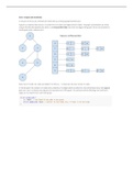
Explanations for use of elements BT
WEEK 1 – SUBSTRUCTURES
1.1 Precast assembled foundation with hollow core floor
• EPS – offers good thermal insulation
• Hallow core floor slab – represents the support for the weight of the building
• Concrete mortar – makes the connection between slabs, and creates an air-tight floor
• Concrete blocks – minimize the contact between the floor slab and foundation, and reduce
heat loss through the floor
• Precast concrete pile – represents an anchor for the building, giving a stable and hard place
to put it on
• Mortar bed – for flattening, and adjusting the height of a pile
• Concrete beam – represents support for the slab, and distributes the load of the building
1.2 Cast-in-place insulated basement
• Galvanized steel – the strip is integrated into the seam for extra waterproofing
• Concrete slab – serves as the distribution of the load
• XPS insulation – serves as a heat saver
• Tongue or grove joint – serves as the connector between insulation panels, and protects
concrete from water
• PE foil – serves as protection from water for insulation
• Rough base for the wall – serves for a better connection between the wall and the floor, and
is adding waterproofing
• Reinforced bars – stick out for a good structural connection between the wall and the floor
• Bitumen – serves as the glue between the insulation and the concrete
WEEK 2 – LIGHT STRUCTURES
2.1 Timber skeleton with timber Lignatur floor
• Lignatur floor – is built from glued panels
• Wooden beams – transfer loads from the slab to the columns
• Wooden columns – transfer loads to the foundation // columns made of wood to carry the
structure
• Insulation – contributes to fire safety, and absorbs sounds
• Steel connector element – makes the connection between the column and foundation
• Concrete pad footing – represents the support for the foundation // carries and spreads
concentrated loads, caused by the column // is enforced with steel rebars in order to connect
with other elements
• Steel rebars – bars that stick out of the concrete to connect other materials like steel and
wood
• Nuts – connect the footing and column through the steel connectors
o Connection between column and beam
▪ Steel connector elements – T-L profiles made out of steel, that form a fixed
connection between the columns and beams
, 2.2 Precast concrete skeleton with timber joist floor
• Console – to support the weight of the beam, and to connect the beam to the column // to
distribute forces
• Timber joists – to support the floor, and are placed perpendicular to the floor to support the
weight and distribute it // to distribute the forces
• Shoe joint – to support the timber joist
• Gaines and steel bars – to connect the beam with the console
• Gaines – holes in the column for the steel rebars to slide in // empty space to slide over the
rebars and fill up with mortar // to connect the column to the beam by forming an opening for
the bar of the column to enter the beam
• Steel rebars – connect the floor and the column using concrete // stick out of the flooring to
form a solid and secure connection between columns and flooring // to connect the column
to the beam by being precast into the column and put in the gaine of the beam
• Plywood floor – to support the weight and load
• Soil-supported floor – with a frost cover of 80 cm of concrete and insulation that also acts as
a form for concrete // a layer of concrete is poured on a layer of insulation to prevent heat
loss; the soil temporarily supports the floors, and afterward the floor will be supported by the
facade
• Solid concrete columns – premade columns from the factory, to support the weight of the
building // solid base made out of concrete
• Air release holes – to ensure that the gaines can be filled up fully with concrete(mortar) and
no air in it(air can escape) // to let the air out when filling the gaines
• Adjustment tiles – to adjust the height and position of the column
• Injection holes – for pouring concrete into the gaines for extra strength for the column // to
connect the floor to the columns, the gaines are filled by using the small injection holes // to
inject mortar into the structure
• Mortar – to connect the column to the beam by surrounding the bar within the gaine
2.3 Steel skeleton with Slimline floor
• Slimline floor slab – distributes the loads applied to it, without deformation or cracking, and
represents a light floor with accessible infrastructure // consists of a layer of concrete to
connect the hollow core slab with accessible gutters to the beams
• Insulation – provides resistance to heat flow, and prevents acoustics from going through the
floor
• Steel beam - gives flexibility to the building, and carries the loads
• M16 bolts – make a steady connection between the beam and the column // a fixed
connection is made
• HE-A 180 columns – support heavy structures // steel columns that are very steady // to
distribute the forces and carry the load of the structure
• Top nuts – to strengthen the connection between the column and the floor, fixed connection
• Head plate – steel plate that is welded to a column to connect the column to a floor using
rebars and bolts // welded plate of steel connected to H-columns to connect the column to
the rebars of the concrete flooring
• Bolds – on the top and bottom of the head plates to connect and stabilize the columns
• Rebars – bars that stick out of concrete to serve as a connection between the floor and the
column // 4 steel bars sticking out of the concrete to enable a fixed connection between the
floor and the columns
• Soil-supported floor – a layer of concrete is poured on a layer of insulation to prevent heat
loss; the soil temporarily supports the floors, and afterward the floor will be supported by the