Learner Name Assessor Name
Date Issued Completion Date Submitted On
Qualification Unit
Unit 57:
Principles and Applications of Analogue Electronics
Pearson BTEC Level 3 Diploma in Unit code: K/600/6744
Electrical/Electronic Engineering(QCF) QCF Level 3: BTEC Nationals
Credit value: 10
Assignment number and title:
Assignment 4: Building and Testing Analogue Circuits
Achieved
Criteria To achieve the criteria the evidence must show that the
Task no. (Assessor to
Reference student is able to
initial & date)
Build and test an electronic circuit to a given analogue
P8 1
circuit specification
Evaluate computer-based and practical methods used to
D2 analyse the behaviour of analogue circuits with respect to 2
their effectiveness in the design process.
, Assignment 4: Building and Testing Analogue Circuits
Task 1
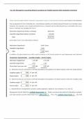
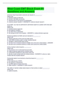
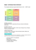
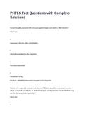
Design and construct a Voltage Controlled oscillator using 555 Timer and display the output
waveform.
Voltage controlled oscillator using a 555 timer with the display output on the oscilloscope
The values of the components I used in the circuit:
Blue capacitor:o.1uf
Yellow capacitor:0.01uf
555 IC timer
Resistor:2.7 kohms
Resistor:10 kohms
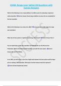
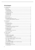
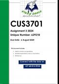
The following image represents the input and output signal of the circuit
Date Issued Completion Date Submitted On
Qualification Unit
Unit 57:
Principles and Applications of Analogue Electronics
Pearson BTEC Level 3 Diploma in Unit code: K/600/6744
Electrical/Electronic Engineering(QCF) QCF Level 3: BTEC Nationals
Credit value: 10
Assignment number and title:
Assignment 4: Building and Testing Analogue Circuits
Achieved
Criteria To achieve the criteria the evidence must show that the
Task no. (Assessor to
Reference student is able to
initial & date)
Build and test an electronic circuit to a given analogue
P8 1
circuit specification
Evaluate computer-based and practical methods used to
D2 analyse the behaviour of analogue circuits with respect to 2
their effectiveness in the design process.
, Assignment 4: Building and Testing Analogue Circuits
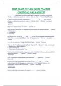
Task 1
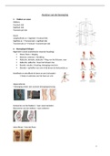
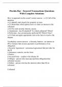
Design and construct a Voltage Controlled oscillator using 555 Timer and display the output
waveform.
Voltage controlled oscillator using a 555 timer with the display output on the oscilloscope
The values of the components I used in the circuit:
Blue capacitor:o.1uf
Yellow capacitor:0.01uf
555 IC timer
Resistor:2.7 kohms
Resistor:10 kohms
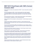
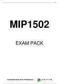
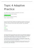
The following image represents the input and output signal of the circuit