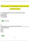
👡
Flip-Flops
Clock
One Bit Memory Cell
Set State / 1 State
Reset State/ 0 State
Latches
SR Latch
Gated SR Latch
Gated D Latch
Flip Flops
Latches V/S Flip Flops
Level Triggering
Positive Level Triggering
Negative Level Triggering
Edge Triggering
Positive Edge Triggering
Negative Edge Triggering
SR Flip-Flop
Positive Edge Triggered SR Flip-Flop
Negative Edge Triggered SR Flip Slop
D Flip Flop/Delay Flip Flop
JK Flip-Flop
Race Around Condition
Master Slave SR Flip Flop
Master Slave JK Flip Flop
T Flip Flop
Preset and Clear
Excitation Tables
SR Flip Flop
JK Flip Flop
D Flip Flop
T Flip Flop
Conversion
SR Flip Flop to D Flip Flop
SR Flip Flop to JK Flip Flop
SR Flip Flop to T Flip Flop
JK Flip Flop to T Flip Flop
JK Flip Flop to D Flip Flop
D Flip Flop to T Flip Flop
T Flip Flop to D Flip Flop
JK Flip Flop to SR Flip Flop
D Flip Flop to SR Flip Flop
T Flip Flop to SR Flip Flop
Flip-Flops 1
, D Flip Flop to JK Flip Flop
Applications of Flip Flops
Clock
Time required to complete one cycle is called clock period or clock cycle
One Bit Memory Cell
If the circuit enters a particular state, it remains in that state , thus it can be used to store 1-bit of digital
information. Therefore, this circuit is also referred to as a latch.
Set State / 1 State
Q = Aˉ = B = 1
ˉ =A=B
Q ˉ=0
Reset State/ 0 State
Q = Aˉ = B = 0
ˉ =A=B
Q ˉ=1
Latches
SR Latch
Flip-Flops 2