An Instructor’s Solutions Manual To Accompany
STEEL DESIGN, 7th Edition
WILLIAM T. SEGUI
, Contents
Preface Vi
Chapter 1 Introduction 1-1
Chapter 2 Concepts In Structural Steel Design 2-1
Chapter 3 Tension Members 3-1
Chapter 4 Compression Members 4-1
Chapter 5 Beams 5-1
Chapter 6 Beam-Columns 6-1
Chapter 7 Simple Connections 7-1
Chapter 8 Eccentric Connections 8-1
Chapter 9 Composite Construction 9-1
Chapter 10 Plate Girders 10-1
, CHAPTER 1 - INTRODUCTION
1.5-1
(a) P = 20(67) = 1340 Lb
F= P = 1340 = 68. 02 Psi F = 68.0 Psi
A 19.
7
(b) Since E = Fϵ ,
68. 02
ϵ= F = = 2. 35 × 10−6 ϵ = 2. 35 × 10−6
E 29, 000,
000
1.5-2
(a) L = 9/ Sin 45 ° = 12. 73 Ft
ΔL = ϵl = 8. 9 × 10−4 × 12. 73 × 12 = 0. 136 In. ΔL = 0. 136 In.
(b) F = ϵe = 8. 9 × 10−4 × 29, 000 = 25. 81 Ksi
P = Fa = 25. 81(1. 31) = 33. 8 Kips P = 33. 8 Kips
1.5-3
(a) A = Лd2 Л(0. 5)2 2
= = 0. 1963 In.
4 4
F = P = 5000 = 25, 470 Psi
A 0.
1963
ϵ= = −36. 792 × = 8. 49 × 10−4
10
ΔL 8
L
E = F = 25, 470 = 3. 0 × 107 Psi E = 30, 000 Ksi
ϵ 8. 49 × 10−4
(b) Fu = Pu = 14, = 74, 900 Psi Fu = 74. 9 Ksi
A 700
0.
1963
[1-1]
© 2013 Cengage Learning. All Rights Reserved. May not be scanned, copied or duplicated, or posted to a publicly accessible website, in whole or in part.
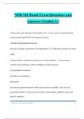
, 1.5-4
Spreadsheet Results:
(A) (B)
Load Stress
(Lb) (Psi) Microstrain
2,000 10,186 47
2,500 12,732 220
3,000 15,279 500
3,500 17,825 950
4,000 20,372 1,111
4,500 22,918 1,200
5,000 25,465 1,702
30,000
25,000
Stress (psi)
20,000
15,000
10,000
5,000
0
0.000000 0.000500 0.001000 0.001500 0.002000
Strain
(c) Slope = 9,210,000 Psi = Modulus Of Elasticity
[1-2]
© 2013 Cengage Learning. All Rights Reserved. May not be scanned, copied or duplicated, or posted to a publicly accessible website, in whole or in part.
STEEL DESIGN, 7th Edition
WILLIAM T. SEGUI
, Contents
Preface Vi
Chapter 1 Introduction 1-1
Chapter 2 Concepts In Structural Steel Design 2-1
Chapter 3 Tension Members 3-1
Chapter 4 Compression Members 4-1
Chapter 5 Beams 5-1
Chapter 6 Beam-Columns 6-1
Chapter 7 Simple Connections 7-1
Chapter 8 Eccentric Connections 8-1
Chapter 9 Composite Construction 9-1
Chapter 10 Plate Girders 10-1
, CHAPTER 1 - INTRODUCTION
1.5-1
(a) P = 20(67) = 1340 Lb
F= P = 1340 = 68. 02 Psi F = 68.0 Psi
A 19.
7
(b) Since E = Fϵ ,
68. 02
ϵ= F = = 2. 35 × 10−6 ϵ = 2. 35 × 10−6
E 29, 000,
000
1.5-2
(a) L = 9/ Sin 45 ° = 12. 73 Ft
ΔL = ϵl = 8. 9 × 10−4 × 12. 73 × 12 = 0. 136 In. ΔL = 0. 136 In.
(b) F = ϵe = 8. 9 × 10−4 × 29, 000 = 25. 81 Ksi
P = Fa = 25. 81(1. 31) = 33. 8 Kips P = 33. 8 Kips
1.5-3
(a) A = Лd2 Л(0. 5)2 2
= = 0. 1963 In.
4 4
F = P = 5000 = 25, 470 Psi
A 0.
1963
ϵ= = −36. 792 × = 8. 49 × 10−4
10
ΔL 8
L
E = F = 25, 470 = 3. 0 × 107 Psi E = 30, 000 Ksi
ϵ 8. 49 × 10−4
(b) Fu = Pu = 14, = 74, 900 Psi Fu = 74. 9 Ksi
A 700
0.
1963
[1-1]
© 2013 Cengage Learning. All Rights Reserved. May not be scanned, copied or duplicated, or posted to a publicly accessible website, in whole or in part.
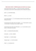
, 1.5-4
Spreadsheet Results:
(A) (B)
Load Stress
(Lb) (Psi) Microstrain
2,000 10,186 47
2,500 12,732 220
3,000 15,279 500
3,500 17,825 950
4,000 20,372 1,111
4,500 22,918 1,200
5,000 25,465 1,702
30,000
25,000
Stress (psi)
20,000
15,000
10,000
5,000
0
0.000000 0.000500 0.001000 0.001500 0.002000
Strain
(c) Slope = 9,210,000 Psi = Modulus Of Elasticity
[1-2]
© 2013 Cengage Learning. All Rights Reserved. May not be scanned, copied or duplicated, or posted to a publicly accessible website, in whole or in part.