1.3 Review Assignment Latches & Flip-
Flops
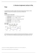
14. Determine the Q waveform relative to the clock if the signals shown in Figure 7–83 are
applied to the inputs of the J-K flip-flop. Assume that Q is initially LOW.
Answers
Q output waveform (starting LOW):
1. 1st falling edge: PRE = LOW → Q = HIGH (asynchronous preset)
2. 2nd falling edge: J = 1, K = 1 → Toggle → Q = LOW
3. 3rd falling edge: CLR = LOW → Q = LOW (asynchronous clear)
4. 4th falling edge: J = 1, K = 0 → Set → Q = HIGH
5. 5th falling edge: J = 0, K = 1 → Reset → Q = LOW
Final Q output:
LOW → HIGH → LOW → LOW → HIGH → LOW
16. The following serial data are applied to the flip-flop through the AND gates as indicated in
Figure 7–85. Determine the resulting serial data that appears on the Q output. There is one
This study source was downloaded by 100000901878207 from CourseHero.com on 10-31-2025 14:49:01 GMT -05:00
https://www.coursehero.com/file/249228691/13-Review-Assignment-updatedocx/
, clock pulse for each bit time. Assume that Q is initially 0 and that:
Answer
Let me trace through the serial data bits (rightmost first) and determine the resulting Q
output:
The given serial data is:
J₁: 1 0 1 0 0 1 1
J₂: 0 1 1 1 0 1 0
J₃: 1 1 1 1 0 0 0
K₁: 0 0 0 1 1 1 0
K₂: 1 1 0 1 1 0 0
K₃: 1 0 1 0 1 0 1
Starting with Q = 0, I'll analyze each bit time:
Bit J₁ J₂ J₃ J K₁ K₂ K₃ K Q(current) Q(next)
1 1 0 0 00 0 1 00 0
2 1 1 0 01 0 0 00 0
3 0 0 0 01 1 1 10 0
4 0 1 1 01 1 0 00 0
5 0 0 1 01 0 1 00 0
6 1 1 1 10 1 0 00 1
This study source was downloaded by 100000901878207 from CourseHero.com on 10-31-2025 14:49:01 GMT -05:00
https://www.coursehero.com/file/249228691/13-Review-Assignment-updatedocx/
Flops
14. Determine the Q waveform relative to the clock if the signals shown in Figure 7–83 are
applied to the inputs of the J-K flip-flop. Assume that Q is initially LOW.
Answers
Q output waveform (starting LOW):
1. 1st falling edge: PRE = LOW → Q = HIGH (asynchronous preset)
2. 2nd falling edge: J = 1, K = 1 → Toggle → Q = LOW
3. 3rd falling edge: CLR = LOW → Q = LOW (asynchronous clear)
4. 4th falling edge: J = 1, K = 0 → Set → Q = HIGH
5. 5th falling edge: J = 0, K = 1 → Reset → Q = LOW
Final Q output:
LOW → HIGH → LOW → LOW → HIGH → LOW
16. The following serial data are applied to the flip-flop through the AND gates as indicated in
Figure 7–85. Determine the resulting serial data that appears on the Q output. There is one
This study source was downloaded by 100000901878207 from CourseHero.com on 10-31-2025 14:49:01 GMT -05:00
https://www.coursehero.com/file/249228691/13-Review-Assignment-updatedocx/
, clock pulse for each bit time. Assume that Q is initially 0 and that:
Answer
Let me trace through the serial data bits (rightmost first) and determine the resulting Q
output:
The given serial data is:
J₁: 1 0 1 0 0 1 1
J₂: 0 1 1 1 0 1 0
J₃: 1 1 1 1 0 0 0
K₁: 0 0 0 1 1 1 0
K₂: 1 1 0 1 1 0 0
K₃: 1 0 1 0 1 0 1
Starting with Q = 0, I'll analyze each bit time:
Bit J₁ J₂ J₃ J K₁ K₂ K₃ K Q(current) Q(next)
1 1 0 0 00 0 1 00 0
2 1 1 0 01 0 0 00 0
3 0 0 0 01 1 1 10 0
4 0 1 1 01 1 0 00 0
5 0 0 1 01 0 1 00 0
6 1 1 1 10 1 0 00 1
This study source was downloaded by 100000901878207 from CourseHero.com on 10-31-2025 14:49:01 GMT -05:00
https://www.coursehero.com/file/249228691/13-Review-Assignment-updatedocx/