
BJTs - COMMON EMITTER AMPLIFIERS
Introduction
• All types of transistor amplifiers operate using AC signal inputs which alternate between a positive and
negative value so some way of ‘presetting’ the amplifier circuit to operate between these two maximum or
peak values is required
• This is achieved through biasing, which is very important in amplifier design as it establishes the correct
operating point of the transistor amplifier ready to receive signals, thereby reducing any distortion to the
output signal
• The aim of any small signal amplifier is to amplify all of the input signal with the minimum amount of
distortion possible to the output signal (in other words, the output signal must be an exact reproduction of the
input signal but only bigger)
• To obtain low distortion when used as an amplifier, the operating Q point needs to be correctly selected;
this is in fact the DC operating point of the amplifier and its position may be established at any point along
the lode line by a suitable biasing arrangement
• The best possible position for this Q point is as close to the centre position of the load line as reasonably
possible, thereby producing a class A type amplifier operation i.e., Vce = 0.5Vcc
The Common Emitter Amplifier Circuit
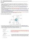
• The signal stage common emitter amplifier circuit uses what is commonly called voltage divider biasing
• This type of biasing arrangement uses two resistors as a potential divider network across the supply with their
centre point supplying the required Base bias voltage to the transistor
• Voltage divider biasing is commonly used in the design of BJT amplifier circuits
This method of biasing the transistor greatly reduces the effects of
varying β by holding the Base bias at a constant steady voltage level
allowing for the best stability
• The quiescent Base voltage (Vb) is determined by the potential divider
network formed by the two resistors (R1, R2) and the power supply
voltage Vcc as shown with the current flowing through both resistors
, • The total resistance RT will be equal to R1 + R2 giving the current as i = Vcc/RT
• The voltage level generated at the junction of the resistors R1 and R2 holds the Base voltage Vb constant at a
value below the supply voltage
• The voltage divider network used in the CE amplifier circuit divides the supply voltage in proportion to the
resistance
• This bias reference voltage can be easily calculated using the simple voltage divider formula:
Transistor Bias Voltage
• The same supply voltage (Vcc) also determines the maximum Collector current (Ic) when the transistor
is switched fully ON (saturation), Vce = 0
• The Base current Ib for the transistor is found from the Collector current, Ic and the DC current gain, β of the
transistor
β is sometimes referred to as the HFE which is the transistors forward current gain in the CE
configuration
• β has no fixed ratio of the two currents Ic and Ib so a small change in the Base current will cause a large
change in the Collector current
• Transistors of the same type and part number will have large variations in their β value; for example, the
BC107 NPN bipolar transistor has a β value of between 110 and 450 (data sheet value), so one BC107 may
have a β of 110 and another may have one of 450 - this is because β is a characteristic of the transistors
construction and not of its operation
• As the Base/Emitter junction is forward biased, the Emitter voltage Ve will be one junction voltage drop
different to the Base voltage Vb
• If the voltage across the Emitter is known then the Emitter current Ie can easily be calculated using Ohm’s
Law
• The Collector current Ic can be approximated, since it is almost the same value as the Emitter current
CE Amplifier Example
A CE amplifier circuit has a load resistance RL of 1.2kΩ and a supply voltage of 12V. Calculate the maximum
Collector current Ic flowing through the load resistor when the transistor is switched fully ON (saturation), assume
Vce = 0. Also find the value of the Emitter resistor if it has a voltage drop of 1V across it. Calculate the values of
all other circuit resistors assuming a standard NPN silicon transistor.
• This then establishes point ‘A’ on the vertical axis of
the characteristics curves and occurs when Vce = 0
• When the transistor is fully OFF, there is no voltage
drop across either resistor Re or RL as no current is
flowing through them; the voltage drop across the
transistor Vce is equal to the supply voltage hence
establishing point ‘B’ on the horizontal axis of the
characteristics curves
Introduction
• All types of transistor amplifiers operate using AC signal inputs which alternate between a positive and
negative value so some way of ‘presetting’ the amplifier circuit to operate between these two maximum or
peak values is required
• This is achieved through biasing, which is very important in amplifier design as it establishes the correct
operating point of the transistor amplifier ready to receive signals, thereby reducing any distortion to the
output signal
• The aim of any small signal amplifier is to amplify all of the input signal with the minimum amount of
distortion possible to the output signal (in other words, the output signal must be an exact reproduction of the
input signal but only bigger)
• To obtain low distortion when used as an amplifier, the operating Q point needs to be correctly selected;
this is in fact the DC operating point of the amplifier and its position may be established at any point along
the lode line by a suitable biasing arrangement
• The best possible position for this Q point is as close to the centre position of the load line as reasonably
possible, thereby producing a class A type amplifier operation i.e., Vce = 0.5Vcc
The Common Emitter Amplifier Circuit
• The signal stage common emitter amplifier circuit uses what is commonly called voltage divider biasing
• This type of biasing arrangement uses two resistors as a potential divider network across the supply with their
centre point supplying the required Base bias voltage to the transistor
• Voltage divider biasing is commonly used in the design of BJT amplifier circuits
This method of biasing the transistor greatly reduces the effects of
varying β by holding the Base bias at a constant steady voltage level
allowing for the best stability
• The quiescent Base voltage (Vb) is determined by the potential divider
network formed by the two resistors (R1, R2) and the power supply
voltage Vcc as shown with the current flowing through both resistors
, • The total resistance RT will be equal to R1 + R2 giving the current as i = Vcc/RT
• The voltage level generated at the junction of the resistors R1 and R2 holds the Base voltage Vb constant at a
value below the supply voltage
• The voltage divider network used in the CE amplifier circuit divides the supply voltage in proportion to the
resistance
• This bias reference voltage can be easily calculated using the simple voltage divider formula:
Transistor Bias Voltage
• The same supply voltage (Vcc) also determines the maximum Collector current (Ic) when the transistor
is switched fully ON (saturation), Vce = 0
• The Base current Ib for the transistor is found from the Collector current, Ic and the DC current gain, β of the
transistor
β is sometimes referred to as the HFE which is the transistors forward current gain in the CE
configuration
• β has no fixed ratio of the two currents Ic and Ib so a small change in the Base current will cause a large
change in the Collector current
• Transistors of the same type and part number will have large variations in their β value; for example, the
BC107 NPN bipolar transistor has a β value of between 110 and 450 (data sheet value), so one BC107 may
have a β of 110 and another may have one of 450 - this is because β is a characteristic of the transistors
construction and not of its operation
• As the Base/Emitter junction is forward biased, the Emitter voltage Ve will be one junction voltage drop
different to the Base voltage Vb
• If the voltage across the Emitter is known then the Emitter current Ie can easily be calculated using Ohm’s
Law
• The Collector current Ic can be approximated, since it is almost the same value as the Emitter current
CE Amplifier Example
A CE amplifier circuit has a load resistance RL of 1.2kΩ and a supply voltage of 12V. Calculate the maximum
Collector current Ic flowing through the load resistor when the transistor is switched fully ON (saturation), assume
Vce = 0. Also find the value of the Emitter resistor if it has a voltage drop of 1V across it. Calculate the values of
all other circuit resistors assuming a standard NPN silicon transistor.
• This then establishes point ‘A’ on the vertical axis of
the characteristics curves and occurs when Vce = 0
• When the transistor is fully OFF, there is no voltage
drop across either resistor Re or RL as no current is
flowing through them; the voltage drop across the
transistor Vce is equal to the supply voltage hence
establishing point ‘B’ on the horizontal axis of the
characteristics curves


