
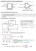
INTRODUCTION: OPERATIONAL AMPLIFIER REPRESENTATIONS
V+
Balance No connection Inverting input
Inverting input V+ Output
Non-inverting input Output
Non-inverting input
V- Balance
Offset, null
OP-AMP PACKAGE V-
OP-AMP SCHEMATIC SYMBOL
BASIC CHARACTERISTICS OF AN IDEAL OP-AMP
1. The potential di erence (voltage) between the inverting and non-inverting terminals is very small and can be
considered to be zero for simpli cation
2. The currents at the inverting and non-inverting terminals are very small and can be considered to be zero for
simpli cation
INVERTING AMPLIFIER: BASIC OPERATION
• Since this is an inverting ampli er, the input signal will
be inverted at the output. If the input voltage is
positive, the output voltage will be negative and vice
versa.
• The only current at point a are from Rf and Ri as
indicated on the diagram
• Since Vinverting is more-or-less equal to Vnon-inverting,
Va = 0.
Using KCL, we can determine that:
Seeing as the current on the inverting terminal is negligible
as per the basic characteristics of an ideal op-amp
We also know from Ohm’s Law that:
Seeing as the potential difference Va = 0V:
THIS RATIO IS WHAT DETERMINES THE AMOUNT OF
AMPLIFICATIO
THIS IS KNOWN AS THE GAIN FACTOR
SIMPLE EXAMPLE:
fi
N
, INVERTING AMPLIFIER: WORKED EXAMPLE
r
From the sinusoidal equation, we can determine the
properties of the signal and visualise the input voltage
against the output voltage...
10Hz represents 10 complete cycles per second
NON-INVERTING AMPLIFIER: BASIC OPERATION
NOTE: Orientation of the input
Using KCL, we can determine that:
Seeing as the current on
the inverting terminal is
negligible as per the basic
characteristics of an ideal
o op-amp
V+
Balance No connection Inverting input
Inverting input V+ Output
Non-inverting input Output
Non-inverting input
V- Balance
Offset, null
OP-AMP PACKAGE V-
OP-AMP SCHEMATIC SYMBOL
BASIC CHARACTERISTICS OF AN IDEAL OP-AMP
1. The potential di erence (voltage) between the inverting and non-inverting terminals is very small and can be
considered to be zero for simpli cation
2. The currents at the inverting and non-inverting terminals are very small and can be considered to be zero for
simpli cation
INVERTING AMPLIFIER: BASIC OPERATION
• Since this is an inverting ampli er, the input signal will
be inverted at the output. If the input voltage is
positive, the output voltage will be negative and vice
versa.
• The only current at point a are from Rf and Ri as
indicated on the diagram
• Since Vinverting is more-or-less equal to Vnon-inverting,
Va = 0.
Using KCL, we can determine that:
Seeing as the current on the inverting terminal is negligible
as per the basic characteristics of an ideal op-amp
We also know from Ohm’s Law that:
Seeing as the potential difference Va = 0V:
THIS RATIO IS WHAT DETERMINES THE AMOUNT OF
AMPLIFICATIO
THIS IS KNOWN AS THE GAIN FACTOR
SIMPLE EXAMPLE:
fi
N
, INVERTING AMPLIFIER: WORKED EXAMPLE
r
From the sinusoidal equation, we can determine the
properties of the signal and visualise the input voltage
against the output voltage...
10Hz represents 10 complete cycles per second
NON-INVERTING AMPLIFIER: BASIC OPERATION
NOTE: Orientation of the input
Using KCL, we can determine that:
Seeing as the current on
the inverting terminal is
negligible as per the basic
characteristics of an ideal
o op-amp


