

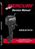
6/8/9.9/10/15
6/8/9.9/10/15
90-827242R02 February 2003
Starting Model Year 1986
Starting Model Year 1986
Serial Number 0A197112 and Up (USA)
09503295 and Up (Belgium)
,Notice
Throughout this publication, Dangers, Warnings and Cautions (accompanied by the
International HAZARD Symbol ) are used to alert the mechanic to special instructions
concerning a particular service or operation that may be hazardous if performed incorrectly
or carelessly. OBSERVE THEM CAREFULLY!
These Safety Alerts alone cannot eliminate the hazards that they signal. Strict compliance
to these special instructions when performing the service, plus Common Sense operation,
are major accident prevention measures.
DANGER
DANGER - Immediate hazards which WILL result in severe personal injury or death.
WARNING
WARNING - Hazards or unsafe practices which COULD result in severe personal
injury or death.
CAUTION
Hazards or unsafe practices which could result in minor personal injury or product
or property damage.
Notice to Users of This Manual
This service manual has been written and published by the Service Department of Mercury
Marine to aid our dealers’ mechanics and company service personnel when servicing the
products described herein.
It is assumed that these personnel are familiar with the servicing procedures of these
products, or like or similar products manufactured and marketed by Mercury Marine, that
they have been trained in the recommended servicing procedures of these products which
includes the use of mechanics’ common hand tools and the special Mercury Marine or
recommended tools from other suppliers.
We could not possibly know of and advise the service trade of all conceivable procedures
by which a service might be performed and of the possible hazards and/or results of each
method. We have not undertaken any such wide evaluation. Therefore, anyone who uses
a service procedure and/or tool, which is not recommended by the manufacturer, first must
completely satisfy himself that neither his nor the products safety will be endangered by the
service procedure selected.
All information, illustrations and specifications contained in this manual are based on the
latest product information available at the time of publication. As required, revisions to this
manual will be sent to all dealers contracted by us to sell and/or service these products.
It should be kept in mind, while working on the product, that the electrical system and ignition
system are capable of violent and damaging short circuits or severe electrical shocks. When
performing any work where electrical terminals could possibly be grounded or touched by
the mechanic, the battery cables should be disconnected at the battery.
Any time the intake or exhaust openings are exposed during service they should be covered
to protect against accidental entrance of foreign material which could enter the cylinders and
cause extensive internal damage when the engine is started.
90-827242R02 FEBRUARY 2003 Page i
, It is important to note, during any maintenance procedure replacement fasteners must have
the same measurements and strength as those removed. Numbers on the heads of the
metric bolts and on the surfaces of metric nuts indicate their strength. American bolts use
radial lines for this purpose, while most American nuts do not have strength markings.
Mismatched or incorrect fasteners can result in damage or malfunction, or possibly personal
injury. Therefore, fasteners removed should be saved for reuse in the same locations
whenever possible. Where the fasteners are not satisfactory for re-use, care should be
taken to select a replacement that matches the original.
Cleanliness and Care of Outboard Motor
A marine power product is a combination of many machined, honed, polished and lapped
surfaces with tolerances that are measured in the ten thousands of an inch/mm. When any
product component is serviced, care and cleanliness are important. Throughout this
manual, it should be understood that proper cleaning, and protection of machined surfaces
and friction areas is a part of the repair procedure. This is considered standard shop practice
even if not specifically stated.
Whenever components are removed for service, they should be retained in order. At the
time of installation, they should be installed in the same locations and with the same mating
surfaces as when removed.
Personnel should not work on or under an outboard which is suspended. Outboards should
be attached to work stands, or lowered to ground as soon as possible.
We reserve the right to make changes to this manual without prior notification.
Refer to dealer service bulletins for other pertinent information concerning the products
described in this manual.
Page ii 90-827242R02 FEBRUARY 2003
, Service Manual Outline
Section 1 - General Information & Specifications
General Information
& Specifications 1
A - Specifications
B - Maintenance
C - General Information
D - Outboard Installation
Electrical and Ignition
2
Section 2 - Electrical and Ignition
A - Ignition System
B - Charging & Starting System
C - Timing/Synchronizing & Adjusting
Fuel System
3
D - Wiring Diagrams
Section 3 - Fuel System
A - Fuel Delivery System
B - Emissions
Powerhead
4
Section 4 - Powerhead
Section 5 - Mid-Section
A - Clamp/Swivel Brackets and Driveshaft Housing
Mid-Section
5
B - Power Trim
Section 6 - Lower Unit
Section 7 - Attachments/Control Linkage
A - Throttle/Shift Linkage (Tiller Handle Shift Models)
Lower Unit
6
B - Throttle/Shift Linkage (Side Shift Models)
C - Tiller Handle
Section 8 - Manual Starter
Attachments/
Control Linkage 7
Manual Starter
8
90-827242R02 FEBRUARY 2003 Page iii
6/8/9.9/10/15
90-827242R02 February 2003
Starting Model Year 1986
Starting Model Year 1986
Serial Number 0A197112 and Up (USA)
09503295 and Up (Belgium)
,Notice
Throughout this publication, Dangers, Warnings and Cautions (accompanied by the
International HAZARD Symbol ) are used to alert the mechanic to special instructions
concerning a particular service or operation that may be hazardous if performed incorrectly
or carelessly. OBSERVE THEM CAREFULLY!
These Safety Alerts alone cannot eliminate the hazards that they signal. Strict compliance
to these special instructions when performing the service, plus Common Sense operation,
are major accident prevention measures.
DANGER
DANGER - Immediate hazards which WILL result in severe personal injury or death.
WARNING
WARNING - Hazards or unsafe practices which COULD result in severe personal
injury or death.
CAUTION
Hazards or unsafe practices which could result in minor personal injury or product
or property damage.
Notice to Users of This Manual
This service manual has been written and published by the Service Department of Mercury
Marine to aid our dealers’ mechanics and company service personnel when servicing the
products described herein.
It is assumed that these personnel are familiar with the servicing procedures of these
products, or like or similar products manufactured and marketed by Mercury Marine, that
they have been trained in the recommended servicing procedures of these products which
includes the use of mechanics’ common hand tools and the special Mercury Marine or
recommended tools from other suppliers.
We could not possibly know of and advise the service trade of all conceivable procedures
by which a service might be performed and of the possible hazards and/or results of each
method. We have not undertaken any such wide evaluation. Therefore, anyone who uses
a service procedure and/or tool, which is not recommended by the manufacturer, first must
completely satisfy himself that neither his nor the products safety will be endangered by the
service procedure selected.
All information, illustrations and specifications contained in this manual are based on the
latest product information available at the time of publication. As required, revisions to this
manual will be sent to all dealers contracted by us to sell and/or service these products.
It should be kept in mind, while working on the product, that the electrical system and ignition
system are capable of violent and damaging short circuits or severe electrical shocks. When
performing any work where electrical terminals could possibly be grounded or touched by
the mechanic, the battery cables should be disconnected at the battery.
Any time the intake or exhaust openings are exposed during service they should be covered
to protect against accidental entrance of foreign material which could enter the cylinders and
cause extensive internal damage when the engine is started.
90-827242R02 FEBRUARY 2003 Page i
, It is important to note, during any maintenance procedure replacement fasteners must have
the same measurements and strength as those removed. Numbers on the heads of the
metric bolts and on the surfaces of metric nuts indicate their strength. American bolts use
radial lines for this purpose, while most American nuts do not have strength markings.
Mismatched or incorrect fasteners can result in damage or malfunction, or possibly personal
injury. Therefore, fasteners removed should be saved for reuse in the same locations
whenever possible. Where the fasteners are not satisfactory for re-use, care should be
taken to select a replacement that matches the original.
Cleanliness and Care of Outboard Motor
A marine power product is a combination of many machined, honed, polished and lapped
surfaces with tolerances that are measured in the ten thousands of an inch/mm. When any
product component is serviced, care and cleanliness are important. Throughout this
manual, it should be understood that proper cleaning, and protection of machined surfaces
and friction areas is a part of the repair procedure. This is considered standard shop practice
even if not specifically stated.
Whenever components are removed for service, they should be retained in order. At the
time of installation, they should be installed in the same locations and with the same mating
surfaces as when removed.
Personnel should not work on or under an outboard which is suspended. Outboards should
be attached to work stands, or lowered to ground as soon as possible.
We reserve the right to make changes to this manual without prior notification.
Refer to dealer service bulletins for other pertinent information concerning the products
described in this manual.
Page ii 90-827242R02 FEBRUARY 2003
, Service Manual Outline
Section 1 - General Information & Specifications
General Information
& Specifications 1
A - Specifications
B - Maintenance
C - General Information
D - Outboard Installation
Electrical and Ignition
2
Section 2 - Electrical and Ignition
A - Ignition System
B - Charging & Starting System
C - Timing/Synchronizing & Adjusting
Fuel System
3
D - Wiring Diagrams
Section 3 - Fuel System
A - Fuel Delivery System
B - Emissions
Powerhead
4
Section 4 - Powerhead
Section 5 - Mid-Section
A - Clamp/Swivel Brackets and Driveshaft Housing
Mid-Section
5
B - Power Trim
Section 6 - Lower Unit
Section 7 - Attachments/Control Linkage
A - Throttle/Shift Linkage (Tiller Handle Shift Models)
Lower Unit
6
B - Throttle/Shift Linkage (Side Shift Models)
C - Tiller Handle
Section 8 - Manual Starter
Attachments/
Control Linkage 7
Manual Starter
8
90-827242R02 FEBRUARY 2003 Page iii


