Chapter 11
Inductance and Magnetic Energy
11.1 Mutual Inductance ............................................................................................ 11-3
Example 11.1 Mutual Inductance of Two Concentric Coplanar Loops ............... 11-5
11.2 Self-Inductance ................................................................................................. 11-5
Example 11.2 Self-Inductance of a Solenoid........................................................ 11-6
Example 11.3 Self-Inductance of a Toroid ........................................................... 11-7
Example 11.4 Mutual Inductance of a Coil Wrapped Around a Solenoid ........... 11-8
11.3 Energy Stored in Magnetic Fields .................................................................. 11-10
Example 11.5 Energy Stored in a Solenoid ........................................................ 11-11
Animation 11.1: Creating and Destroying Magnetic Energy............................ 11-12
Animation 11.2: Magnets and Conducting Rings ............................................. 11-13
11.4 RL Circuits ...................................................................................................... 11-15
11.4.1 Self-Inductance and the Modified Kirchhoff's Loop Rule....................... 11-15
11.4.2 Rising Current.......................................................................................... 11-18
11.4.3 Decaying Current ..................................................................................... 11-20
11.5 LC Oscillations ............................................................................................... 11-21
11.6 The RLC Series Circuit ................................................................................... 11-26
11.7 Summary......................................................................................................... 11-28
11.8 Appendix 1: General Solutions for the RLC Series Circuit ............................ 11-30
11.8.1 Quality Factor .......................................................................................... 11-32
11.9 Appendix 2: Stresses Transmitted by Magnetic Fields .................................. 11-33
Animation 11.3: A Charged Particle in a Time-Varying Magnetic Field ......... 11-37
11.10 Problem-Solving Strategies .......................................................................... 11-38
11.10.1 Calculating Self-Inductance................................................................... 11-38
11.10.2 Circuits containing inductors ................................................................. 11-39
11.11 Solved Problems ........................................................................................... 11-39
11.11.1 Energy stored in a toroid........................................................................ 11-39
11.11.2 Magnetic Energy Density ...................................................................... 11-40
11.11.3 Mutual Inductance ................................................................................. 11-41
11.11.4 RL Circuit............................................................................................... 11-42
11.11.5 RL Circuit............................................................................................... 11-44
11.11.6 LC Circuit............................................................................................... 11-45
11.12 Conceptual Questions ................................................................................... 11-47
11-1
,11.13 Additional Problems ..................................................................................... 11-48
11.13.1 Solenoid ................................................................................................. 11-48
11.13.2 Self-Inductance ...................................................................................... 11-48
11.13.3 Coupled Inductors.................................................................................. 11-48
11.13.4 RL Circuit............................................................................................... 11-49
11.13.5 RL Circuit............................................................................................... 11-50
11.13.6 Inductance of a Solenoid With and Without Iron Core ......................... 11-50
11.13.7 RLC Circuit ............................................................................................ 11-51
11.13.8 Spinning Cylinder .................................................................................. 11-52
11.13.9 Spinning Loop........................................................................................ 11-52
11-2
, Inductance and Magnetic Energy
11.1 Mutual Inductance
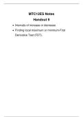
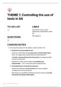
Suppose two coils are placed near each other, as shown in Figure 11.1.1
Figure 11.1.1 Changing current in coil 1 produces changing magnetic flux in coil 2.
G
The first coil has N1 turns and carries a current I1 which gives rise to a magnetic field B1 .
Since the two coils are close to each other, some of the magnetic field lines through coil 1
will also pass through coil 2. Let Φ 21 denote the magnetic flux through one turn of coil 2
due to I1. Now, by varying I1 with time, there will be an induced emf associated with the
changing magnetic flux in the second coil:
d Φ 21 d G G
ε 21 = − N 2
dt
=− ∫∫
dt coil 2
B1 ⋅ dA 2 (11.1.1)
The time rate of change of magnetic flux Φ 21 in coil 2 is proportional to the time rate of
change of the current in coil 1:
d Φ 21 dI
N2 = M 21 1 (11.1.2)
dt dt
where the proportionality constant M 21 is called the mutual inductance. It can also be
written as
N 2 Φ 21
M 21 = (11.1.3)
I1
The SI unit for inductance is the henry (H):
11-3
, 1 henry = 1 H = 1 T ⋅ m 2 /A (11.1.4)
We shall see that the mutual inductance M 21 depends only on the geometrical properties
of the two coils such as the number of turns and the radii of the two coils.
In a similar manner, suppose instead there is a current I2 in the second coil and it is
varying with time (Figure 11.1.2). Then the induced emf in coil 1 becomes
d Φ12 d G G
ε12 = − N1
dt
=− ∫∫
dt coil 1
B 2 ⋅ dA1 (11.1.5)
and a current is induced in coil 1.
Figure 11.1.2 Changing current in coil 2 produces changing magnetic flux in coil 1.
This changing flux in coil 1 is proportional to the changing current in coil 2,
d Φ12 dI
N1 = M 12 2 (11.1.6)
dt dt
where the proportionality constant M 12 is another mutual inductance and can be written
as
N1Φ12
M 12 = (11.1.7)
I2
However, using the reciprocity theorem which combines Ampere’s law and the Biot-
Savart law, one may show that the constants are equal:
M 12 = M 21 ≡ M (11.1.8)
11-4
Inductance and Magnetic Energy
11.1 Mutual Inductance ............................................................................................ 11-3
Example 11.1 Mutual Inductance of Two Concentric Coplanar Loops ............... 11-5
11.2 Self-Inductance ................................................................................................. 11-5
Example 11.2 Self-Inductance of a Solenoid........................................................ 11-6
Example 11.3 Self-Inductance of a Toroid ........................................................... 11-7
Example 11.4 Mutual Inductance of a Coil Wrapped Around a Solenoid ........... 11-8
11.3 Energy Stored in Magnetic Fields .................................................................. 11-10
Example 11.5 Energy Stored in a Solenoid ........................................................ 11-11
Animation 11.1: Creating and Destroying Magnetic Energy............................ 11-12
Animation 11.2: Magnets and Conducting Rings ............................................. 11-13
11.4 RL Circuits ...................................................................................................... 11-15
11.4.1 Self-Inductance and the Modified Kirchhoff's Loop Rule....................... 11-15
11.4.2 Rising Current.......................................................................................... 11-18
11.4.3 Decaying Current ..................................................................................... 11-20
11.5 LC Oscillations ............................................................................................... 11-21
11.6 The RLC Series Circuit ................................................................................... 11-26
11.7 Summary......................................................................................................... 11-28
11.8 Appendix 1: General Solutions for the RLC Series Circuit ............................ 11-30
11.8.1 Quality Factor .......................................................................................... 11-32
11.9 Appendix 2: Stresses Transmitted by Magnetic Fields .................................. 11-33
Animation 11.3: A Charged Particle in a Time-Varying Magnetic Field ......... 11-37
11.10 Problem-Solving Strategies .......................................................................... 11-38
11.10.1 Calculating Self-Inductance................................................................... 11-38
11.10.2 Circuits containing inductors ................................................................. 11-39
11.11 Solved Problems ........................................................................................... 11-39
11.11.1 Energy stored in a toroid........................................................................ 11-39
11.11.2 Magnetic Energy Density ...................................................................... 11-40
11.11.3 Mutual Inductance ................................................................................. 11-41
11.11.4 RL Circuit............................................................................................... 11-42
11.11.5 RL Circuit............................................................................................... 11-44
11.11.6 LC Circuit............................................................................................... 11-45
11.12 Conceptual Questions ................................................................................... 11-47
11-1
,11.13 Additional Problems ..................................................................................... 11-48
11.13.1 Solenoid ................................................................................................. 11-48
11.13.2 Self-Inductance ...................................................................................... 11-48
11.13.3 Coupled Inductors.................................................................................. 11-48
11.13.4 RL Circuit............................................................................................... 11-49
11.13.5 RL Circuit............................................................................................... 11-50
11.13.6 Inductance of a Solenoid With and Without Iron Core ......................... 11-50
11.13.7 RLC Circuit ............................................................................................ 11-51
11.13.8 Spinning Cylinder .................................................................................. 11-52
11.13.9 Spinning Loop........................................................................................ 11-52
11-2
, Inductance and Magnetic Energy
11.1 Mutual Inductance
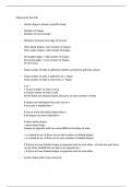
Suppose two coils are placed near each other, as shown in Figure 11.1.1
Figure 11.1.1 Changing current in coil 1 produces changing magnetic flux in coil 2.
G
The first coil has N1 turns and carries a current I1 which gives rise to a magnetic field B1 .
Since the two coils are close to each other, some of the magnetic field lines through coil 1
will also pass through coil 2. Let Φ 21 denote the magnetic flux through one turn of coil 2
due to I1. Now, by varying I1 with time, there will be an induced emf associated with the
changing magnetic flux in the second coil:
d Φ 21 d G G
ε 21 = − N 2
dt
=− ∫∫
dt coil 2
B1 ⋅ dA 2 (11.1.1)
The time rate of change of magnetic flux Φ 21 in coil 2 is proportional to the time rate of
change of the current in coil 1:
d Φ 21 dI
N2 = M 21 1 (11.1.2)
dt dt
where the proportionality constant M 21 is called the mutual inductance. It can also be
written as
N 2 Φ 21
M 21 = (11.1.3)
I1
The SI unit for inductance is the henry (H):
11-3
, 1 henry = 1 H = 1 T ⋅ m 2 /A (11.1.4)
We shall see that the mutual inductance M 21 depends only on the geometrical properties
of the two coils such as the number of turns and the radii of the two coils.
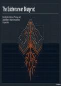
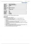
In a similar manner, suppose instead there is a current I2 in the second coil and it is
varying with time (Figure 11.1.2). Then the induced emf in coil 1 becomes
d Φ12 d G G
ε12 = − N1
dt
=− ∫∫
dt coil 1
B 2 ⋅ dA1 (11.1.5)
and a current is induced in coil 1.
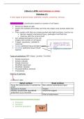
Figure 11.1.2 Changing current in coil 2 produces changing magnetic flux in coil 1.
This changing flux in coil 1 is proportional to the changing current in coil 2,
d Φ12 dI
N1 = M 12 2 (11.1.6)
dt dt
where the proportionality constant M 12 is another mutual inductance and can be written
as
N1Φ12
M 12 = (11.1.7)
I2
However, using the reciprocity theorem which combines Ampere’s law and the Biot-
Savart law, one may show that the constants are equal:
M 12 = M 21 ≡ M (11.1.8)
11-4