ME341 EXPERIMENT 5 TRANSIENT ANALYSIS |
COMPREHENSIVE EXAM FOR YR. 2026/2027
ME 341-Experimental Methods in Mechanical Engineering Experiment
#5: Transient Behavior Analysis
1 Introduction
In this experiment, transient system behavior is investigated for both first- and second-order
systems. Two types of first-order systems are investigated: thermal and electrical. In the thermal
system, the transient response of a thermocouple is examined while a resistor-capacitor (RC)
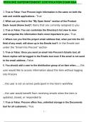
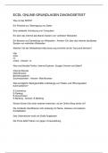
circuit is examined for the electrical system. For the second-order system, a single system is
investigated: an inductor-resistor-capacitor (LRC) circuit as shown in Figure 1.
Figure 1. Example of a simple second-order system: an LRC circuit.
In each of the three systems, a step input is used for excitation to investigate the transient
response. For each system, the transient behavior is measured experimentally and used to
determine time domain parameters which quantify the transient behavior. For the first-order
systems, the system’s time constant and frequency bandwidth are also estimated. For the
second-order systems, these include the time constant, ringing frequency, damping, 95%
response time, and maximum overshoot percentage.
2 Equipment
Each of the four laboratory stations in 3290 SELE are equipped with the following:
• Function generator
• DC Power supply
• High-Z Voltage Follower
• Record exact values from Breadboard. Breadboard with the following values:
, Page 2 of 23
o Resistor: 470 Ω ± 0.3% o
Capacitor 1: ~0.06 μF ± 2% o
Capacitor 2: ~0.6 μF ±2% o
Capacitor 3: ~6 μF ± 2% o
Inductor: 470 mH ± 5%
• F BNC to dual banana jack adaptor: QTY 1
• 36” long, M-M dual banana plug coaxial cable
• 18” long, 22 AWG wire with banana plug: QTY 4
• 12” long, 22 AWG wire: QTY 4
• 6” long, 22 AWG jumper wire: QTY 4
• 1/4” Flat head screw driver
• Data acquisition system
• 36” M-M Mini-B to A USB 1.0 cable
• Laboratory computer with the following software:
o Windaq Data Acquisition
Software o Windaq Dashboard o
Microsoft Excel
• K type thermocouple, uncovered tip
• K type thermocouple, covered tip
• Thermocouple connector
• Thermocouple amplifier
• Ice bath reservoir
• Ice bath containment pan
• Ice
• Cooler
3 Procedure
Prior to your laboratory session, all instrumentation is checked for function and accuracy. Come
prepared to lab by reading the lab manual, watching the overview video on Blackboard, and
reviewing the data collection spreadsheet. Measure the temperature and relative humidity to
ensure stable room conditions during testing.
3.1 Part A: Thermal System Transient Response
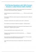
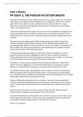
The transient thermal response is investigated in Part A using a thermocouple. A diagram of the
electrical setup for Part A is shown in Figure 2 and a more detailed illustration of the
thermocouple and the ice bath is shown in Figure 3.
, Page 3 of 23
Figure 2. Diagram of the thermocouple system used in Part A.
COMPREHENSIVE EXAM FOR YR. 2026/2027
ME 341-Experimental Methods in Mechanical Engineering Experiment
#5: Transient Behavior Analysis
1 Introduction
In this experiment, transient system behavior is investigated for both first- and second-order
systems. Two types of first-order systems are investigated: thermal and electrical. In the thermal
system, the transient response of a thermocouple is examined while a resistor-capacitor (RC)
circuit is examined for the electrical system. For the second-order system, a single system is
investigated: an inductor-resistor-capacitor (LRC) circuit as shown in Figure 1.
Figure 1. Example of a simple second-order system: an LRC circuit.
In each of the three systems, a step input is used for excitation to investigate the transient
response. For each system, the transient behavior is measured experimentally and used to
determine time domain parameters which quantify the transient behavior. For the first-order
systems, the system’s time constant and frequency bandwidth are also estimated. For the
second-order systems, these include the time constant, ringing frequency, damping, 95%
response time, and maximum overshoot percentage.
2 Equipment
Each of the four laboratory stations in 3290 SELE are equipped with the following:
• Function generator
• DC Power supply
• High-Z Voltage Follower
• Record exact values from Breadboard. Breadboard with the following values:
, Page 2 of 23
o Resistor: 470 Ω ± 0.3% o
Capacitor 1: ~0.06 μF ± 2% o
Capacitor 2: ~0.6 μF ±2% o
Capacitor 3: ~6 μF ± 2% o
Inductor: 470 mH ± 5%
• F BNC to dual banana jack adaptor: QTY 1
• 36” long, M-M dual banana plug coaxial cable
• 18” long, 22 AWG wire with banana plug: QTY 4
• 12” long, 22 AWG wire: QTY 4
• 6” long, 22 AWG jumper wire: QTY 4
• 1/4” Flat head screw driver
• Data acquisition system
• 36” M-M Mini-B to A USB 1.0 cable
• Laboratory computer with the following software:
o Windaq Data Acquisition
Software o Windaq Dashboard o
Microsoft Excel
• K type thermocouple, uncovered tip
• K type thermocouple, covered tip
• Thermocouple connector
• Thermocouple amplifier
• Ice bath reservoir
• Ice bath containment pan
• Ice
• Cooler
3 Procedure
Prior to your laboratory session, all instrumentation is checked for function and accuracy. Come
prepared to lab by reading the lab manual, watching the overview video on Blackboard, and
reviewing the data collection spreadsheet. Measure the temperature and relative humidity to
ensure stable room conditions during testing.
3.1 Part A: Thermal System Transient Response
The transient thermal response is investigated in Part A using a thermocouple. A diagram of the
electrical setup for Part A is shown in Figure 2 and a more detailed illustration of the
thermocouple and the ice bath is shown in Figure 3.
, Page 3 of 23
Figure 2. Diagram of the thermocouple system used in Part A.