ALL 7 CHAPTERS & Appendix A, B & C. COVERED
FIGURES
, Appendix A
Instruction Set Principles
© 2019 Elsevier Inc. All rights reserved.
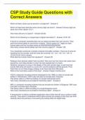
,Figure A.1 Operand locations for four instruction set architecture classes. The arrows indicate whether the
operand is an input or the result of the arithmetic-logical unit (ALU) operation, or both an input and result. Lighter shades
indicate inputs, and the dark shade indicates the result. In (A), a top of stack (TOS) register points to the top input
operand, which is combined with the operand below. The first operand is removed from the stack, the result takes the
place of the second operand, and TOS is updated to point to the result. All operands are implicit. In (B), the accumulator
is both an implicit input operand and a result. In (C), one input operand is a register, one is in memory, and the result
goes to a register. All operands are registers in (D) and, like the stack architecture, can be transferred to memory only via
separate instructions: push or pop for (A) and load or store for (D).
© 2019 Elsevier Inc. All rights reserved. 2
, Figure A.2 The code sequence for C = A + B for four classes of instruction sets. Note that the Add instruction has
implicit operands for stack and accumulator architectures and explicit operands for register architectures. It is assumed that
A, B, and C all belong in memory and that the values of A and B cannot be destroyed. Figure A.1 shows the Add operation
for each class of architecture.
© 2019 Elsevier Inc. All rights reserved. 3
FIGURES
, Appendix A
Instruction Set Principles
© 2019 Elsevier Inc. All rights reserved.
,Figure A.1 Operand locations for four instruction set architecture classes. The arrows indicate whether the
operand is an input or the result of the arithmetic-logical unit (ALU) operation, or both an input and result. Lighter shades
indicate inputs, and the dark shade indicates the result. In (A), a top of stack (TOS) register points to the top input
operand, which is combined with the operand below. The first operand is removed from the stack, the result takes the
place of the second operand, and TOS is updated to point to the result. All operands are implicit. In (B), the accumulator
is both an implicit input operand and a result. In (C), one input operand is a register, one is in memory, and the result
goes to a register. All operands are registers in (D) and, like the stack architecture, can be transferred to memory only via
separate instructions: push or pop for (A) and load or store for (D).
© 2019 Elsevier Inc. All rights reserved. 2
, Figure A.2 The code sequence for C = A + B for four classes of instruction sets. Note that the Add instruction has
implicit operands for stack and accumulator architectures and explicit operands for register architectures. It is assumed that
A, B, and C all belong in memory and that the values of A and B cannot be destroyed. Figure A.1 shows the Add operation
for each class of architecture.
© 2019 Elsevier Inc. All rights reserved. 3