Basic Electrical & Electronics Engineering (MU • Sem 1)
(Single Phase Transfo rmer) p
·· · age no, (3.2)
.., 3.1 WORKING PRINCIPLE OF A SINGLE linked hy common nux .
PHASE TRANSFORMER • It consi~l of two inductive coil ~ which , •
are c1cctncal ly
: uo. Explain the working principle of a TrnnRformor. : sepa,atctl hul 111agnc1ically linked thmugh . . h
I a pat of low
I I 1cllh:ta11cc. The two coil~ rn,,c, high m11 tu· I ·
I .J In(1uctance
----- ----- ----- ----- --- ----- --·~- ----- ----- I
'M'.
• A transformer is a ~tatil: ckctrk al apparatus which can
transfer power in one dn·uil Into l'l,•ctrkul pmwr of
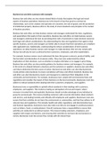
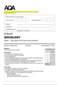
• lf one coi l is co1111cc tcd lo alt ernating vr,lt;ige \<Jurce
then ~mall alternating magnct 11.ing c.urrcr,t now,
the same fre-quenc,· to anollll'l' drcult . It can
through it there hy ~etting 11p alternating flux <!J in the
raise/lower the \\)hage with C0rresponding
111ag11ctic core mo~t of which get~ linked with r,ther c, iJ
decrease/increa~e in the current. 1
in which a mutually induced e.m.f. i~ prriduc.ed a, per
• The physical basis of transformer is Faraday's laws of
Faraday's laws of E.M.I. and given bye= - M 2!.
E.M.I. and mutual induction between the two circuits dt ·
T
1-$AC
supply
V1 O--+ -'n=
P2
Primary..,__ _ _ _ _ _ _ _..,. Secondary
winding winding
(101 )Fig. 3.1.1 : Working principle of a transformer
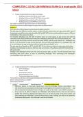
Primary Laminated iron core
:--01tage__ _ Secondary
lf.Olt<ige
I
r··
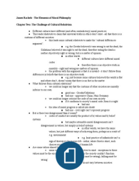
---- --# --....A.G. -o Voltage level
rn ·, - , . - - - - ~ - changes but
-- -~~pply .:l ! frequen cy i.e.,
time period T
remains same
flux($)
Fig 3.1.l(a) : Working Principle of a Transformer
• If the second coil is closed through load then current I (iv) Where the two electrical circuits are in mutual
flows through it and hence the electrical energy is inductive innuence of each other.
transferred entirely magnetically from first coil to
second coil. .., 3.2 TRANSFORMER CONSTRUCTION
• In brief, a transformer is a static electrical apparatus that
(i) Transfers electric power from one circuit to
~ ~ - • E~p-l;i~-th ; ~~~;t;u~~i~~ ~f- ;i~g-1; ~hase transformer. :
I •
I
another,
I---- ----- ----- ----- ----- ----- ----- -- ----- -
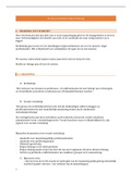
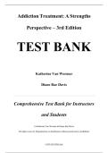
(i) The various parts of a transformer can be represe nted
(ii) It does so without a change of frequency, with the help of the following chart :
(iii) It does this by electromagnetic induction and,
(New Syllabus w.e.f Academic Year 24·2S)(Ml·03)
rd
, (': 11!; f•t,,;,111 IMri~f,,,rr1•1r)
1
f'll 'I" WJ (:J -3)
111
( I ll l f>I 1111• 1 " 11 ' l\p•· h ,111 ,f,,1rrn·r-,, 11,,. v 1n• llf•i/ i •,111ri•IJll• I J
~--
',r 1•111 " 1lir ,.,,,. 1111111 11 1rt .,Jwl I lyf'<"
i llthh!r-t ti I '
lt ,1tl', f,., 111, ,,
I · ,,,,,... 11, ,,,11,, l, ,1 ,,,,,.,f,•r,Ut:
111
f'"'''""
ill) 11 1 llw 11 111, I 111)1 1, ,lt10\( II Ill 1hr f 111 l ] l
~•.t)l' \t>!l\'
l...., · ,( \'l~\ I •11111111111,t \
-~~~ \ :>-·
1•,l•.i·J..
I ,, r1
~'"''·'
tii [fil;;, :.~ <
......'Ii~!-\ ,n ,!,r 'J
► loqh ,,,'M ,_.
,n,,,1 a·v,r.
,~mr rLAtrllnAWI ( .WI
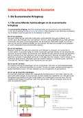
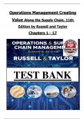
\I ) ('orr l ) fl(' trnn, fornwr
- LOW voltag"
w1nd1ng
High voi!ag.,
,:, 1 l:t :ill ~ ~re:'~ ~,( tr.inst~,011;.•rs. tht• l'~'l\' is l:l'llstrul'l\'d ,nsulaticn
.(. tr'J.,~·,'flllCr ~t st'°'·I l;uninati\111s :1sscn1bkll w
rr,,\i.k .1 \'\.'lltinuoos m:1~netk rath with:\ mininllllll (lf (ii) Slwll type transformer
(104)1-'ig, J.2.J
.i:=-~.lt' i~lu.iN-
,, , The st~l u.d i~ l'f hi~h sili~()l\ ~ontent, S\)111cti111cs
~ 3.2.1 Comparison between Core Type
trJl ~.itN tCI pfC'<iu~e a hi~h pcrmealiility and a tow and Shell Type Transformer
~~~mas
k 1~-s at the usual operating tlux Jensitks. The ------------------------•
--------core
I---- Compare -----
NJ~ cwttnt loss is (minimised t,y laminating the c0re.
: ua. type and shell type transformers :
~ 1lmi0.1rions ~ins insulated from each 01hcr t,y a
'
: W(any1 i-t4?dtM®tl•itW•ef#♦H
four points).
£M-·fr',ffl! :'
li&hl C('.1( of ,·amish or tiy llfl oxide layer on the surf;1L't'. l -- --- -- --------- ------------ --- ----- -- ---1
Shdl type transformer
The thid.ness of laminations varies frmn Cort' type
Sr.
trunsformcr
No. Used for suppl} ing pO\\ t'L
OJS lO 0.5 mm.
Used for distritllltilw
Tn,1..tonn« types I.
of elt.'ctrical t' nergy.
It i, ·ON ' only \\hl'n
II is ·ON ' throughout
2. ~xn\er i, requireJ.
(ii) 1he Jay.
(i) Shell type !I, dtil'ienl'} i, high
Co,etype (used for power II 's effiL·it'ncy is k,,
3. bt'l\l \'l'II 90'1- Ill l)S'1·.
(usedfor~ appiie8uon l @501;: .
d eleclric8I energy) ll is u,t'.l by inJi \ iJuJ.1
II is ust'd by t'll•.:1ril'i1y
4. ni-1,1111.:rs e.g. 11ek!i11g
boards :111.I big ~twp,. U1:1chine slwps etc.
ht) Coastructionally, lbl ~ are of ,wo general i11~1a1t,11iu11, .
5. Tl1l'Y are .:o, tly, lnll " Y They are n1111par:11ively
types. distinguished flOID each other inerelY ~Y the
anJ 11on-p,1r1ahk . d 1eaper, .:ompact and
manner in which t11e- j,!iilllt'I and secondary coals art portabk .
placed around the lad tH ~eel core-
The types of Jlll:;Jr.lD&fonner consiructions are
two
bon u Ci) Coro ~ (ii) Shell Type, and shown
.... Pia, 3.l.2, 24-2S)(Ml•03)
(Single Phase Transfo rmer) p
·· · age no, (3.2)
.., 3.1 WORKING PRINCIPLE OF A SINGLE linked hy common nux .
PHASE TRANSFORMER • It consi~l of two inductive coil ~ which , •
are c1cctncal ly
: uo. Explain the working principle of a TrnnRformor. : sepa,atctl hul 111agnc1ically linked thmugh . . h
I a pat of low
I I 1cllh:ta11cc. The two coil~ rn,,c, high m11 tu· I ·
I .J In(1uctance
----- ----- ----- ----- --- ----- --·~- ----- ----- I
'M'.
• A transformer is a ~tatil: ckctrk al apparatus which can
transfer power in one dn·uil Into l'l,•ctrkul pmwr of
• lf one coi l is co1111cc tcd lo alt ernating vr,lt;ige \<Jurce
then ~mall alternating magnct 11.ing c.urrcr,t now,
the same fre-quenc,· to anollll'l' drcult . It can
through it there hy ~etting 11p alternating flux <!J in the
raise/lower the \\)hage with C0rresponding
111ag11ctic core mo~t of which get~ linked with r,ther c, iJ
decrease/increa~e in the current. 1
in which a mutually induced e.m.f. i~ prriduc.ed a, per
• The physical basis of transformer is Faraday's laws of
Faraday's laws of E.M.I. and given bye= - M 2!.
E.M.I. and mutual induction between the two circuits dt ·
T
1-$AC
supply
V1 O--+ -'n=
P2
Primary..,__ _ _ _ _ _ _ _..,. Secondary
winding winding
(101 )Fig. 3.1.1 : Working principle of a transformer
Primary Laminated iron core
:--01tage__ _ Secondary
lf.Olt<ige
I
r··
---- --# --....A.G. -o Voltage level
rn ·, - , . - - - - ~ - changes but
-- -~~pply .:l ! frequen cy i.e.,
time period T
remains same
flux($)
Fig 3.1.l(a) : Working Principle of a Transformer
• If the second coil is closed through load then current I (iv) Where the two electrical circuits are in mutual
flows through it and hence the electrical energy is inductive innuence of each other.
transferred entirely magnetically from first coil to
second coil. .., 3.2 TRANSFORMER CONSTRUCTION
• In brief, a transformer is a static electrical apparatus that
(i) Transfers electric power from one circuit to
~ ~ - • E~p-l;i~-th ; ~~~;t;u~~i~~ ~f- ;i~g-1; ~hase transformer. :
I •
I
another,
I---- ----- ----- ----- ----- ----- ----- -- ----- -
(i) The various parts of a transformer can be represe nted
(ii) It does so without a change of frequency, with the help of the following chart :
(iii) It does this by electromagnetic induction and,
(New Syllabus w.e.f Academic Year 24·2S)(Ml·03)
rd
, (': 11!; f•t,,;,111 IMri~f,,,rr1•1r)
1
f'll 'I" WJ (:J -3)
111
( I ll l f>I 1111• 1 " 11 ' l\p•· h ,111 ,f,,1rrn·r-,, 11,,. v 1n• llf•i/ i •,111ri•IJll• I J
~--
',r 1•111 " 1lir ,.,,,. 1111111 11 1rt .,Jwl I lyf'<"
i llthh!r-t ti I '
lt ,1tl', f,., 111, ,,
I · ,,,,,... 11, ,,,11,, l, ,1 ,,,,,.,f,•r,Ut:
111
f'"'''""
ill) 11 1 llw 11 111, I 111)1 1, ,lt10\( II Ill 1hr f 111 l ] l
~•.t)l' \t>!l\'
l...., · ,( \'l~\ I •11111111111,t \
-~~~ \ :>-·
1•,l•.i·J..
I ,, r1
~'"''·'
tii [fil;;, :.~ <
......'Ii~!-\ ,n ,!,r 'J
► loqh ,,,'M ,_.
,n,,,1 a·v,r.
,~mr rLAtrllnAWI ( .WI
\I ) ('orr l ) fl(' trnn, fornwr
- LOW voltag"
w1nd1ng
High voi!ag.,
,:, 1 l:t :ill ~ ~re:'~ ~,( tr.inst~,011;.•rs. tht• l'~'l\' is l:l'llstrul'l\'d ,nsulaticn
.(. tr'J.,~·,'flllCr ~t st'°'·I l;uninati\111s :1sscn1bkll w
rr,,\i.k .1 \'\.'lltinuoos m:1~netk rath with:\ mininllllll (lf (ii) Slwll type transformer
(104)1-'ig, J.2.J
.i:=-~.lt' i~lu.iN-
,, , The st~l u.d i~ l'f hi~h sili~()l\ ~ontent, S\)111cti111cs
~ 3.2.1 Comparison between Core Type
trJl ~.itN tCI pfC'<iu~e a hi~h pcrmealiility and a tow and Shell Type Transformer
~~~mas
k 1~-s at the usual operating tlux Jensitks. The ------------------------•
--------core
I---- Compare -----
NJ~ cwttnt loss is (minimised t,y laminating the c0re.
: ua. type and shell type transformers :
~ 1lmi0.1rions ~ins insulated from each 01hcr t,y a
'
: W(any1 i-t4?dtM®tl•itW•ef#♦H
four points).
£M-·fr',ffl! :'
li&hl C('.1( of ,·amish or tiy llfl oxide layer on the surf;1L't'. l -- --- -- --------- ------------ --- ----- -- ---1
Shdl type transformer
The thid.ness of laminations varies frmn Cort' type
Sr.
trunsformcr
No. Used for suppl} ing pO\\ t'L
OJS lO 0.5 mm.
Used for distritllltilw
Tn,1..tonn« types I.
of elt.'ctrical t' nergy.
It i, ·ON ' only \\hl'n
II is ·ON ' throughout
2. ~xn\er i, requireJ.
(ii) 1he Jay.
(i) Shell type !I, dtil'ienl'} i, high
Co,etype (used for power II 's effiL·it'ncy is k,,
3. bt'l\l \'l'II 90'1- Ill l)S'1·.
(usedfor~ appiie8uon l @501;: .
d eleclric8I energy) ll is u,t'.l by inJi \ iJuJ.1
II is ust'd by t'll•.:1ril'i1y
4. ni-1,1111.:rs e.g. 11ek!i11g
boards :111.I big ~twp,. U1:1chine slwps etc.
ht) Coastructionally, lbl ~ are of ,wo general i11~1a1t,11iu11, .
5. Tl1l'Y are .:o, tly, lnll " Y They are n1111par:11ively
types. distinguished flOID each other inerelY ~Y the
anJ 11on-p,1r1ahk . d 1eaper, .:ompact and
manner in which t11e- j,!iilllt'I and secondary coals art portabk .
placed around the lad tH ~eel core-
The types of Jlll:;Jr.lD&fonner consiructions are
two
bon u Ci) Coro ~ (ii) Shell Type, and shown
.... Pia, 3.l.2, 24-2S)(Ml•03)