Recap PhoMT
Marrit
January 2025
1 Lecture 1 - Diodes
Adapters: reduce voltage, change AC/DC Also, high voltage is necessary for transportation of electricity, as
2
Ploss = I ∗ Rwire , so to transport sufficient power, P = IV, voltage needs to be high.
Contains a transformer, rectifier, and capacitor.
Transformers: turn the 230 V AC into mean = 9 V AC with only positive jumps. Two coils with magnetic
field, different amount of turns -¿ different amount of V transferred (V1 /V2 = n1 /n2 ).
Transformation towards 9 V, -¿ P = VRM S IRM S RMS: Root-Mean-Square value, effective value for calcu-
lating the average power.
AC: oscillates as a sin-function around V=0 DC: jumps up and down from V=0
Rectifier: contains 4 diodes that make sure the current-flow remains in the right direction (square formed,
4 diodes), No negative I, AC becomes only positive.
Capacitor: store charge in parallel capacitors (Capacitance (C) in Farad). These level out the sin-function
that is the voltage over time - gather charge with high voltage on the + side, release when this disappears.
Lessens amplitude.
Diodes: contain a p-type/n-type connected to each other (pn-junction). P-type: positive (anode), n-type:
negative (cathode), only one-way traffic.
In normal operation: Shockley diode equation holds, where the reverse current is near (approximately) zero.
It describes how with a forward bias, the current exponentially increases, and with a reverse bias, there is a
small, constant reverse current.
Changes with heat: electron-hole pairs are thermally dependent. It relates the diode current with the reverse
bias saturation current, which is a type of reverse leakage current.
Current/voltage graph:
• Forward current: going in the positive direction, very little voltage necessary to increase drastically.
(Normal operation window - otherwise damage)
• Leakage current: current is reversed, but breakdown voltage/avalanche current has not yet been reached,
very little current is allowed.
• Breakdown voltage: amount of voltage that diode reverses/allows for avalanche current.
• Approximated using no conductance (1/R) when I = negative, and very high conductance with a fixed
forward voltage drop of Vd .
• Vd = the slight voltage that is needed to get the diode going, diode only functions when the signal
amplitude is bigger than the voltage drop.
1.1 Crash Course Quantum
Atom model: electrons have spin-up or spin-down; Pauli Exclusion principle: each atomic orbital/state/level
can only contain one of either (spin-up/down). Spinning causes slight magnetic field. (Sz = ± 21 h̄).
e only stay at the lowest levels, because temperature needs to be high enough for there to be enough atomic
movement, i.e. movement within levels, to go to higher states. Space between levels is too high on Earth.
ipx x
Wave-particle duality: φ = A · e h̄ = A · eikx = cos(kx) + isin(kx) describes its position as a plane
h
wave, where h̄ = 2π is a constant. This is derived from Schrödinger’s equation setting the potential energy to be
0, since the electrons are free particles (no change in potential energy), this can be solved to be the previously
given equation.
When one uses φ∗χ, where χ is dependent on the angular frequency, one can determine the propagation speed
by fixing a constant phase kx-ωt, as the dx/dt derivative, phase velocity, is then simply ω/k, as x = +ωt+C k .
Thought of as two pairs of plane waves going opposite directions, so two different directions (superposition)
would give a total of 2cos(kx) if added together.
1
, Probability density: |φ(x)|2 = chance the electron will be at the position. Can be described using
a particle in a box model (only 1D - x-axis). The higher up, the more potential energy is needed (V(x)).
Available levels can be filled with one of either spin-orientation.
Each level is an extra half wavelength for every n (standing waves). Schrödinger’s equation: because the
2nd ODE becomes itself (circular), the particles must also be waves.
Tunnel effect : electron waves can go through a potential barrier (tunneling) when in isolated potential
wells. Within it are possible energy levels before reaching V = V0 . If the width of the barrier is small enough,
the particle can be in both and reach an even longer wavelength -¿ lower energy.
Lots of wells: lots of bands for eigenvalues (bands and band gaps). Each band represents a possible energy
level for an isolated well. Due to Heisenberg uncertainty relation (∆x · ∆p ≥ h̄/2) , creating a larger possible
space, means lower possible momentum/kinetic energy. The upper line represents a higher k-value because the
standing waves have shorter wavelength, and thus a larger k, leading to larger energy needed.
1.2 Bands in conductors
Equilibrium value: ”average value” of energy in an energy band. This is defined by properties of the entire
crystal, such as binding energy defining the lattice constant of the crystal.
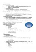
Fill the lowest available states (least energy needed) until the material is electrically neutral (e− = p+ ):
• Metal: highest filled level (in E) is the middle of a band (high conductance)
• Insulator: highest filled level is at the top of a band, with a large gap above (low conductance)
• Semiconductor: highest filled level is at the top, with a small gap on top. Conductance is dependent
on thermal excitation, further enhanced by doping (small amount of other elements in the crystal) or
absorption of light.
Band Diagram: small bias voltage, enter with a bit of extra energy, can leave with up to this energy below
the Fermi level. Fermi energy: Maximum amount of energy between levels - kinetic energy of the highest
occupied state when all unoccupied stationary states are filled is the Fermi Energy.
Band diagram: valence band (all filled levels), conduction band (with lowest levels filled, upper empty)
for semiconductors. With thermal excitation, electrons can go to the conduction band.
Photo-electric effect: photons get absorbed, which causes photo excitation of the electrons to the con-
duction band. This creates metal-like filling of the bands. Also reverse is possible, if they fall back a level, the
difference in energy between the levels will result in the energy of a photon (Ephoton = hf ).
Dopants: best dopants are those that fit into the structure but have more e− (n dopants or electron doping),
or one less e− in the outer shell (p-doping or hole doping) than the semiconductor.
N-dopants donate their electron to the semiconductor, so the electrons are called donors. The bottom layer
of the conduction band becomes more reasonably filled, giving conduction similar to metals.
P-dopants accept an electron from the system, so that a hole frees for transport, these atoms are acceptors.
Top of the valence band now has holes, giving the intrinsic semiconductor metallic conductance qualities.
Holes behave as positively charged particles.
1.3 PN-junctions
Connecting p and n-type dopants (extra holes vs. extra electrons) causes a transfer of electrons from n to p,
since this is the lower energy state. Causes for a depletion region, which acts as a thin insulating layer where
the valence band is completely full and the conduction band empty.
Where the electrons left: positively charged, where they arrived: negatively charged. I.e. a built-in electrical
field. Properties similar to an intrinsic semiconductor -¿ diode behavior.
Positive bias voltage: n-p direction,pushes electrons back into their original spot, thinner depletion region,
other way, it becomes thicker.
2 Lecture 2: MOSFET’s, CMOS, Transistors, Solar Cells
Intrinsic semiconductor: completely empty conduction band, completely filled valence band.
2.1 MOSFET: Metal Oxide on Silicon Field Effect Transistor
=Amplify electric signal
N-channel MOSFETs have a channel made out of p-type that starts to behave as n-type material as it
conducts: charge carriers in the conduction band.
2
Marrit
January 2025
1 Lecture 1 - Diodes
Adapters: reduce voltage, change AC/DC Also, high voltage is necessary for transportation of electricity, as
2
Ploss = I ∗ Rwire , so to transport sufficient power, P = IV, voltage needs to be high.
Contains a transformer, rectifier, and capacitor.
Transformers: turn the 230 V AC into mean = 9 V AC with only positive jumps. Two coils with magnetic
field, different amount of turns -¿ different amount of V transferred (V1 /V2 = n1 /n2 ).
Transformation towards 9 V, -¿ P = VRM S IRM S RMS: Root-Mean-Square value, effective value for calcu-
lating the average power.
AC: oscillates as a sin-function around V=0 DC: jumps up and down from V=0
Rectifier: contains 4 diodes that make sure the current-flow remains in the right direction (square formed,
4 diodes), No negative I, AC becomes only positive.
Capacitor: store charge in parallel capacitors (Capacitance (C) in Farad). These level out the sin-function
that is the voltage over time - gather charge with high voltage on the + side, release when this disappears.
Lessens amplitude.
Diodes: contain a p-type/n-type connected to each other (pn-junction). P-type: positive (anode), n-type:
negative (cathode), only one-way traffic.
In normal operation: Shockley diode equation holds, where the reverse current is near (approximately) zero.
It describes how with a forward bias, the current exponentially increases, and with a reverse bias, there is a
small, constant reverse current.
Changes with heat: electron-hole pairs are thermally dependent. It relates the diode current with the reverse
bias saturation current, which is a type of reverse leakage current.
Current/voltage graph:
• Forward current: going in the positive direction, very little voltage necessary to increase drastically.
(Normal operation window - otherwise damage)
• Leakage current: current is reversed, but breakdown voltage/avalanche current has not yet been reached,
very little current is allowed.
• Breakdown voltage: amount of voltage that diode reverses/allows for avalanche current.
• Approximated using no conductance (1/R) when I = negative, and very high conductance with a fixed
forward voltage drop of Vd .
• Vd = the slight voltage that is needed to get the diode going, diode only functions when the signal
amplitude is bigger than the voltage drop.
1.1 Crash Course Quantum
Atom model: electrons have spin-up or spin-down; Pauli Exclusion principle: each atomic orbital/state/level
can only contain one of either (spin-up/down). Spinning causes slight magnetic field. (Sz = ± 21 h̄).
e only stay at the lowest levels, because temperature needs to be high enough for there to be enough atomic
movement, i.e. movement within levels, to go to higher states. Space between levels is too high on Earth.
ipx x
Wave-particle duality: φ = A · e h̄ = A · eikx = cos(kx) + isin(kx) describes its position as a plane
h
wave, where h̄ = 2π is a constant. This is derived from Schrödinger’s equation setting the potential energy to be
0, since the electrons are free particles (no change in potential energy), this can be solved to be the previously
given equation.
When one uses φ∗χ, where χ is dependent on the angular frequency, one can determine the propagation speed
by fixing a constant phase kx-ωt, as the dx/dt derivative, phase velocity, is then simply ω/k, as x = +ωt+C k .
Thought of as two pairs of plane waves going opposite directions, so two different directions (superposition)
would give a total of 2cos(kx) if added together.
1
, Probability density: |φ(x)|2 = chance the electron will be at the position. Can be described using
a particle in a box model (only 1D - x-axis). The higher up, the more potential energy is needed (V(x)).
Available levels can be filled with one of either spin-orientation.
Each level is an extra half wavelength for every n (standing waves). Schrödinger’s equation: because the
2nd ODE becomes itself (circular), the particles must also be waves.
Tunnel effect : electron waves can go through a potential barrier (tunneling) when in isolated potential
wells. Within it are possible energy levels before reaching V = V0 . If the width of the barrier is small enough,
the particle can be in both and reach an even longer wavelength -¿ lower energy.
Lots of wells: lots of bands for eigenvalues (bands and band gaps). Each band represents a possible energy
level for an isolated well. Due to Heisenberg uncertainty relation (∆x · ∆p ≥ h̄/2) , creating a larger possible
space, means lower possible momentum/kinetic energy. The upper line represents a higher k-value because the
standing waves have shorter wavelength, and thus a larger k, leading to larger energy needed.
1.2 Bands in conductors
Equilibrium value: ”average value” of energy in an energy band. This is defined by properties of the entire
crystal, such as binding energy defining the lattice constant of the crystal.
Fill the lowest available states (least energy needed) until the material is electrically neutral (e− = p+ ):
• Metal: highest filled level (in E) is the middle of a band (high conductance)
• Insulator: highest filled level is at the top of a band, with a large gap above (low conductance)
• Semiconductor: highest filled level is at the top, with a small gap on top. Conductance is dependent
on thermal excitation, further enhanced by doping (small amount of other elements in the crystal) or
absorption of light.
Band Diagram: small bias voltage, enter with a bit of extra energy, can leave with up to this energy below
the Fermi level. Fermi energy: Maximum amount of energy between levels - kinetic energy of the highest
occupied state when all unoccupied stationary states are filled is the Fermi Energy.
Band diagram: valence band (all filled levels), conduction band (with lowest levels filled, upper empty)
for semiconductors. With thermal excitation, electrons can go to the conduction band.
Photo-electric effect: photons get absorbed, which causes photo excitation of the electrons to the con-
duction band. This creates metal-like filling of the bands. Also reverse is possible, if they fall back a level, the
difference in energy between the levels will result in the energy of a photon (Ephoton = hf ).
Dopants: best dopants are those that fit into the structure but have more e− (n dopants or electron doping),
or one less e− in the outer shell (p-doping or hole doping) than the semiconductor.
N-dopants donate their electron to the semiconductor, so the electrons are called donors. The bottom layer
of the conduction band becomes more reasonably filled, giving conduction similar to metals.
P-dopants accept an electron from the system, so that a hole frees for transport, these atoms are acceptors.
Top of the valence band now has holes, giving the intrinsic semiconductor metallic conductance qualities.
Holes behave as positively charged particles.
1.3 PN-junctions
Connecting p and n-type dopants (extra holes vs. extra electrons) causes a transfer of electrons from n to p,
since this is the lower energy state. Causes for a depletion region, which acts as a thin insulating layer where
the valence band is completely full and the conduction band empty.
Where the electrons left: positively charged, where they arrived: negatively charged. I.e. a built-in electrical
field. Properties similar to an intrinsic semiconductor -¿ diode behavior.
Positive bias voltage: n-p direction,pushes electrons back into their original spot, thinner depletion region,
other way, it becomes thicker.
2 Lecture 2: MOSFET’s, CMOS, Transistors, Solar Cells
Intrinsic semiconductor: completely empty conduction band, completely filled valence band.
2.1 MOSFET: Metal Oxide on Silicon Field Effect Transistor
=Amplify electric signal
N-channel MOSFETs have a channel made out of p-type that starts to behave as n-type material as it
conducts: charge carriers in the conduction band.
2