Solution Manual for Control Systems Engineering,
8th Edition by Norman S. Nise All Chapters
Covered, Latest Edition
Copyright © 2011 by John Wiley & Sons, Inc.
,Table of Content
Acknowledgments
Chapter 1: Introduction
Chapter 2: Modeling in the Frequency Domain
Chapter 3: Modeling in the Time Domain
Chapter 4: Time Response
Chapter 5: Reduction of Multiple Subsystems
Chapter 6: Stability
Chapter 7: Steady-State Errors
Chapter 8: Root Locus Techniques
Chapter 9: Design via Root Locus
Chapter 10: Frequency Response Techniques
Chapter 11: Design via Frequency Response
Chapter 12: Design via State Space
Chapter 13: Digital Control Systems
Copyright © 2011 by John Wiley & Sons, Inc.
, Introduction
ANSWERS TO REVIEW QUESTIONS
1. Guided missiles, automatic gain control in radio receivers, satellite tracking antenna
2. Yes - power gain, remote control, parameter conversion; No - Expense, complexity
3. Motor, low pass filter, inertia supported between two bearings
4. Closed-loop systems compensate for disturbances by measuring the response, comparing it tothe
input response (the desired output), and then correcting the output response.
5. Under the condition that the feedback element is other than unity
6. Actuating signal
7. Multiple subsystems can time share the controller. Any adjustments to the controller can be
implemented with simply software changes.
8. Stability, transient response, and steady-state error
9. Steady-state, transient
10. It follows a growing transient response until the steady-state response is no longer visible. The
system will either destroy itself, reach an equilibrium state because of saturation in driving amplifiers,
or hit limit stops.
11. Natural response
12. Determine the transient response performance of the system.
13. Determine system parameters to meet the transient response specifications for the system.
14. True
15. Transfer function, state-space, differential equations
16. Transfer function - the Laplace transform of the differential equation
State-space - representation of an nth order differential equation as n simultaneous first-order
differential equations
Differential equation - Modeling a system with its differential equation
SOLUTIONS TO PROBLEMS
50 volts
1. Five turns yields 50 v. Therefore K = = 1.59
5 x 2 πrad
Copyright © 2011 by John Wiley & Sons, Inc.
, 1-2 Chapter 1: Introduction
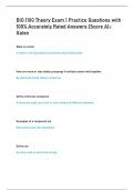
2.
Desired Temperature Voltage Actual
Fuelflow
temperature difference difference temperature
+ Amplifier and
Thermostat Heater
valves
-
3.
Desired Input Error Aileron Roll Roll
roll voltage voltage position rate angle
angle
+ Aileron Aircraft
Pilot Integrate
position dynamics
controls
control
-
Gyro
Gyro voltage
4.
Input
Speed
Desired voltage Actual
Error Motor
speed voltage and speed
transducer +
Amplifier drive
system
-
Dancer
Dancer
position
Voltage dynamics
sensor
proportional
to actual speed
Copyright © 2011 by John Wiley & Sons, Inc.
8th Edition by Norman S. Nise All Chapters
Covered, Latest Edition
Copyright © 2011 by John Wiley & Sons, Inc.
,Table of Content
Acknowledgments
Chapter 1: Introduction
Chapter 2: Modeling in the Frequency Domain
Chapter 3: Modeling in the Time Domain
Chapter 4: Time Response
Chapter 5: Reduction of Multiple Subsystems
Chapter 6: Stability
Chapter 7: Steady-State Errors
Chapter 8: Root Locus Techniques
Chapter 9: Design via Root Locus
Chapter 10: Frequency Response Techniques
Chapter 11: Design via Frequency Response
Chapter 12: Design via State Space
Chapter 13: Digital Control Systems
Copyright © 2011 by John Wiley & Sons, Inc.
, Introduction
ANSWERS TO REVIEW QUESTIONS
1. Guided missiles, automatic gain control in radio receivers, satellite tracking antenna
2. Yes - power gain, remote control, parameter conversion; No - Expense, complexity
3. Motor, low pass filter, inertia supported between two bearings
4. Closed-loop systems compensate for disturbances by measuring the response, comparing it tothe
input response (the desired output), and then correcting the output response.
5. Under the condition that the feedback element is other than unity
6. Actuating signal
7. Multiple subsystems can time share the controller. Any adjustments to the controller can be
implemented with simply software changes.
8. Stability, transient response, and steady-state error
9. Steady-state, transient
10. It follows a growing transient response until the steady-state response is no longer visible. The
system will either destroy itself, reach an equilibrium state because of saturation in driving amplifiers,
or hit limit stops.
11. Natural response
12. Determine the transient response performance of the system.
13. Determine system parameters to meet the transient response specifications for the system.
14. True
15. Transfer function, state-space, differential equations
16. Transfer function - the Laplace transform of the differential equation
State-space - representation of an nth order differential equation as n simultaneous first-order
differential equations
Differential equation - Modeling a system with its differential equation
SOLUTIONS TO PROBLEMS
50 volts
1. Five turns yields 50 v. Therefore K = = 1.59
5 x 2 πrad
Copyright © 2011 by John Wiley & Sons, Inc.
, 1-2 Chapter 1: Introduction
2.
Desired Temperature Voltage Actual
Fuelflow
temperature difference difference temperature
+ Amplifier and
Thermostat Heater
valves
-
3.
Desired Input Error Aileron Roll Roll
roll voltage voltage position rate angle
angle
+ Aileron Aircraft
Pilot Integrate
position dynamics
controls
control
-
Gyro
Gyro voltage
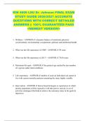
4.
Input
Speed
Desired voltage Actual
Error Motor
speed voltage and speed
transducer +
Amplifier drive
system
-
Dancer
Dancer
position
Voltage dynamics
sensor
proportional
to actual speed
Copyright © 2011 by John Wiley & Sons, Inc.