AQA_2024: A-level Physics - Paper 3
Section B Electronics.
(Merged Question Paper and Marking Scheme)
Please write clearly in block capitals.
Centre number Candidate number
Surname
Forename(s)
Candidate signatu re
I declare this is my own work.
A-level
PHYSICS
Paper 3
Section B Electronics
Monday 17 June 2024 Morning Time allowed: The total time for
Materials
both sections of this paper is
For this paper you must have: 2 hours. You are advised to
a pencil and a ruler spend approximately
a scientific calculator
a Data and Formulae Booklet 50 minutes on this section.
a protractor.
For Examiner’s Use
Instructions
Use black ink or black ball-point pen. Question Mark
Fill in the boxes at the top of this page. 1
Answer all questions.
2
You must answer the questions in the spaces provided. Do not write
outside the box around each page or on blank pages. 3 IB/M/Jun24/E8
If you need extra space for your answer(s), use the lined pages at the end of 4
this book. Write the question number against your answer(s). 5
Do all rough work in this book. Cross through any work you do not want
to be marked. TOTAL
Show all your working.
Information
The marks for questions are shown in brackets.
The maximum mark for this paper is 35.
You are expected to use a scientific calculator where appropriate.
A Data and Formulae Booklet is provided as a loose insert.
,Key areas:
1. Semiconductors:
o Intrinsic and Extrinsic Semiconductors: Understand the
difference between pure (intrinsic) semiconductors and doped
7408/3BE
(extrinsic) semiconductors, and how doping affects conductivity.
o n-type and p-type Semiconductors: Review the behavior of
charge carriers in these types of semiconductors and how they
are created by doping with specific elements.
2. Diodes:
o Working of a Diode: Study the function of a diode in forward
and reverse bias, focusing on current flow and the formation of
the depletion region.
o Applications: Know the practical uses of diodes, such as in
rectifiers for converting AC to DC and light-emitting diodes
(LEDs).
3. Transistors:
o Bipolar Junction Transistor (BJT): Understand the operation
of both NPN and PNP transistors, focusing on the current flow
and the role of the base, collector, and emitter.
o Transistor as a Switch and Amplifier: Learn how BJTs work
in amplifiers and as digital switches in circuits, including the
concepts of active, cutoff, and saturation regions.
4. Capacitors:
o Capacitance and Energy Stored: Review the equation for
capacitance and the relationship between charge, voltage, and
capacitance. Understand the energy stored in a capacitor.
o RC Circuits: Study the charging and discharging processes of
capacitors in RC circuits and the time constant (τ = RC).
5. Operational Amplifiers (Op-Amps):
o Basic Operation: Understand the ideal and non-ideal
characteristics of op-amps, and know their uses in inverting, non-
inverting amplifiers, and other configurations.
o Feedback and Gain: Focus on the concept of feedback in
amplifiers and how it determines the gain.
6. Digital Electronics:
o Logic Gates: Revise the basic logic gates (AND, OR, NOT,
NAND, NOR, XOR, XNOR) and their truth tables.
o Combinational Circuits: Understand how logic gates combine
to form more complex digital systems.
By revising these areas, you will have a comprehensive understanding of
electronics in physics, covering both theoretical concepts and practical
applications.
, 2
Do not write
outside the
Section B box
Answer all questions in this section.
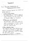
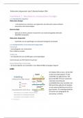
0 1 A toy manufacturer is designing a two-tone siren for use in small battery-operated
cars.
Figure 1 shows design Option 1.
Option 1 uses three separate signal generators feeding into a logic sub-system.
The signal generators produce logic-compatible 9 V square waves of frequencies
1024 Hz, 1 Hz and 512 Hz.
Figure 1
The waveforms shown are not to scale.
0 1
. 1 Explain how the logic level applied at B in Figure 1 determines the output frequency
at Q.
[2 marks]
0 1 . 2 Write the Boolean algebra expression for output Q in terms of the inputs A, B and C.
Use only the logic operations shown in Figure 1.
[2 marks]
Q=
IB/M/Jun24/7408/3BE
, 3
Do not write
outside the
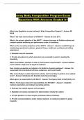
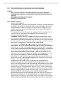
0 1 . 3 Option 1 is tested by replacing the 1 Hz signal generator with a manual input. box
The manual input is provided by the combination of a push-to-make switch
and a 10 kΩ resistor.
The combination produces the following voltages at its output:
0 V when the switch is not pressed
9 V when the switch is pressed.
Figure 2 shows the symbol for the push-to-make switch.
Figure 2
Complete Figure 3 to show how this switch and the 10 kΩ resistor are connected.
Label the output Vout.
You do not need to add details taken from Figure 1.
[1 mark]
Figure 3
Question 1 continues on the next page
Turn over ►
IB/M/Jun24/7408/3BE
Section B Electronics.
(Merged Question Paper and Marking Scheme)
Please write clearly in block capitals.
Centre number Candidate number
Surname
Forename(s)
Candidate signatu re
I declare this is my own work.
A-level
PHYSICS
Paper 3
Section B Electronics
Monday 17 June 2024 Morning Time allowed: The total time for
Materials
both sections of this paper is
For this paper you must have: 2 hours. You are advised to
a pencil and a ruler spend approximately
a scientific calculator
a Data and Formulae Booklet 50 minutes on this section.
a protractor.
For Examiner’s Use
Instructions
Use black ink or black ball-point pen. Question Mark
Fill in the boxes at the top of this page. 1
Answer all questions.
2
You must answer the questions in the spaces provided. Do not write
outside the box around each page or on blank pages. 3 IB/M/Jun24/E8
If you need extra space for your answer(s), use the lined pages at the end of 4
this book. Write the question number against your answer(s). 5
Do all rough work in this book. Cross through any work you do not want
to be marked. TOTAL
Show all your working.
Information
The marks for questions are shown in brackets.
The maximum mark for this paper is 35.
You are expected to use a scientific calculator where appropriate.
A Data and Formulae Booklet is provided as a loose insert.
,Key areas:
1. Semiconductors:
o Intrinsic and Extrinsic Semiconductors: Understand the
difference between pure (intrinsic) semiconductors and doped
7408/3BE
(extrinsic) semiconductors, and how doping affects conductivity.
o n-type and p-type Semiconductors: Review the behavior of
charge carriers in these types of semiconductors and how they
are created by doping with specific elements.
2. Diodes:
o Working of a Diode: Study the function of a diode in forward
and reverse bias, focusing on current flow and the formation of
the depletion region.
o Applications: Know the practical uses of diodes, such as in
rectifiers for converting AC to DC and light-emitting diodes
(LEDs).
3. Transistors:
o Bipolar Junction Transistor (BJT): Understand the operation
of both NPN and PNP transistors, focusing on the current flow
and the role of the base, collector, and emitter.
o Transistor as a Switch and Amplifier: Learn how BJTs work
in amplifiers and as digital switches in circuits, including the
concepts of active, cutoff, and saturation regions.
4. Capacitors:
o Capacitance and Energy Stored: Review the equation for
capacitance and the relationship between charge, voltage, and
capacitance. Understand the energy stored in a capacitor.
o RC Circuits: Study the charging and discharging processes of
capacitors in RC circuits and the time constant (τ = RC).
5. Operational Amplifiers (Op-Amps):
o Basic Operation: Understand the ideal and non-ideal
characteristics of op-amps, and know their uses in inverting, non-
inverting amplifiers, and other configurations.
o Feedback and Gain: Focus on the concept of feedback in
amplifiers and how it determines the gain.
6. Digital Electronics:
o Logic Gates: Revise the basic logic gates (AND, OR, NOT,
NAND, NOR, XOR, XNOR) and their truth tables.
o Combinational Circuits: Understand how logic gates combine
to form more complex digital systems.
By revising these areas, you will have a comprehensive understanding of
electronics in physics, covering both theoretical concepts and practical
applications.
, 2
Do not write
outside the
Section B box
Answer all questions in this section.
0 1 A toy manufacturer is designing a two-tone siren for use in small battery-operated
cars.
Figure 1 shows design Option 1.
Option 1 uses three separate signal generators feeding into a logic sub-system.
The signal generators produce logic-compatible 9 V square waves of frequencies
1024 Hz, 1 Hz and 512 Hz.
Figure 1
The waveforms shown are not to scale.
0 1
. 1 Explain how the logic level applied at B in Figure 1 determines the output frequency
at Q.
[2 marks]
0 1 . 2 Write the Boolean algebra expression for output Q in terms of the inputs A, B and C.
Use only the logic operations shown in Figure 1.
[2 marks]
Q=
IB/M/Jun24/7408/3BE
, 3
Do not write
outside the
0 1 . 3 Option 1 is tested by replacing the 1 Hz signal generator with a manual input. box
The manual input is provided by the combination of a push-to-make switch
and a 10 kΩ resistor.
The combination produces the following voltages at its output:
0 V when the switch is not pressed
9 V when the switch is pressed.
Figure 2 shows the symbol for the push-to-make switch.
Figure 2
Complete Figure 3 to show how this switch and the 10 kΩ resistor are connected.
Label the output Vout.
You do not need to add details taken from Figure 1.
[1 mark]
Figure 3
Question 1 continues on the next page
Turn over ►
IB/M/Jun24/7408/3BE