Unit 6 Single Phase AC Assignment 5
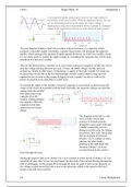
A p-n junction diode connected in series to the load resistor is
essentially a half way rectifier. With the diagrams below, we can
see an alternating current as the input; the input voltage is
displayed as a step down transformer & the resultant is a reduced
output of the transformer that gives to the diode & load resistor.
The next diagram displays a half wave rectifier with an inclusion of a capacitor, which
produces a smoother output. Essentially, a greater load current will discharge the capacitor
rapidly, which upsurges the amount of ripples gained. However, in a half way rectifier circuit,
it’s not really useful to reduce the ripple voltage by smoothing the capacitor, but, it’ll be most
beneficial in a full wave rectifier.
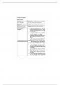
The raw DC delivered by a rectifier on its own would consist of a sequence of half sine waves
with the voltage altering between zero and √2 times the RMS voltage; but this does not
include any diodes & other losses. Furthermore, a supply of this type wouldn’t be much use
for powering circuits due to the fact that analogue circuits would contain a large level of
ripples that are covered on the output, & digital circuits wouldn’t be able to work as the
power is removed every time there is a half cycle.
To smooth the output of the rectifier a reservoir capacitor is used which is placed across the
output of the reciter & is parallel with the load; Normally, the capacitor charges up when the
voltage from the rectifier
rises above that of the
capacitor & as the
rectifier voltage depletes,
the capacitor offers the
required current that
comes from its stored
charge.
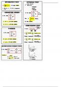
The diagram on the left is a full
wave rectifier circuit that
consists of 4 diodes that are
arranged in series pairs with only
2 diodes conducting current
during ever half cycle. So, during
the positive half cycle, the diodes
that are pointing downwards
(Diodes 1 & 2) conduct in series,
whereas the other diodes
pointing in the right hand side
direction (Diodes 3 & 4) are
reversed biased & the current
flows through the load.
During the negative half cycle, diodes 3 & 4 now conduct in series, however diodes 1 & 2 are
switched off since they’re now reverse biased; the direction of the current flowing through the
load is unchanged. As the current flows through the load, the path is only in one direction, so
the voltage created across the load is also in one direction, which is the same for the last 2
diodes in the full wave rectifier.
D1 Fahim Mohammed
A p-n junction diode connected in series to the load resistor is
essentially a half way rectifier. With the diagrams below, we can
see an alternating current as the input; the input voltage is
displayed as a step down transformer & the resultant is a reduced
output of the transformer that gives to the diode & load resistor.
The next diagram displays a half wave rectifier with an inclusion of a capacitor, which
produces a smoother output. Essentially, a greater load current will discharge the capacitor
rapidly, which upsurges the amount of ripples gained. However, in a half way rectifier circuit,
it’s not really useful to reduce the ripple voltage by smoothing the capacitor, but, it’ll be most
beneficial in a full wave rectifier.
The raw DC delivered by a rectifier on its own would consist of a sequence of half sine waves
with the voltage altering between zero and √2 times the RMS voltage; but this does not
include any diodes & other losses. Furthermore, a supply of this type wouldn’t be much use
for powering circuits due to the fact that analogue circuits would contain a large level of
ripples that are covered on the output, & digital circuits wouldn’t be able to work as the
power is removed every time there is a half cycle.
To smooth the output of the rectifier a reservoir capacitor is used which is placed across the
output of the reciter & is parallel with the load; Normally, the capacitor charges up when the
voltage from the rectifier
rises above that of the
capacitor & as the
rectifier voltage depletes,
the capacitor offers the
required current that
comes from its stored
charge.
The diagram on the left is a full
wave rectifier circuit that
consists of 4 diodes that are
arranged in series pairs with only
2 diodes conducting current
during ever half cycle. So, during
the positive half cycle, the diodes
that are pointing downwards
(Diodes 1 & 2) conduct in series,
whereas the other diodes
pointing in the right hand side
direction (Diodes 3 & 4) are
reversed biased & the current
flows through the load.
During the negative half cycle, diodes 3 & 4 now conduct in series, however diodes 1 & 2 are
switched off since they’re now reverse biased; the direction of the current flowing through the
load is unchanged. As the current flows through the load, the path is only in one direction, so
the voltage created across the load is also in one direction, which is the same for the last 2
diodes in the full wave rectifier.
D1 Fahim Mohammed