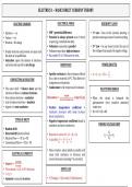
ELECTRICS
1
–
BASIC
DIRECT
CURRENY
THEORY
ELECTRIC
CHARGES
ELECTRICAL
FORCE
KIRCHOFF’S
LAWS
• Electron
=
-‐-‐
ve
• EMF
/
potential
difference
• 1
Law
=
Sum
of
the
currents
entering
a
st
• Proton
=
+
ve
• Potential
is
always
present
even
if
circuit
junction
must
equal
sum
of
currents
exiting.
• Neutron
=
No
charge
is
open
(eg/
waterfall
and
dam)
• Voltmeter
connected
in
parallel
• 2nd
Law
=
In
any
closed
circuit
the
sum
of
• Usually
electrons
and
protons
are
equal
and
• Voltmeter
must
have
high
resistance.
the
voltage
drops
equals
the
supply
voltage.
the
atom
is
in
equilibrium.
• Has
symbol
V
or
U.
Measured
in
volts.
• Ionization
upsets
the
balance
of
electrons
and
atom
ends
up
with
a
net
charge.
RESISTANCE
POWER
(WATTS)
!!
• Specific
resistance
is
the
resistance
offered
• 𝑃 = 𝑉 𝑥 𝐼 = 𝐼 ! 𝑅 =
!
CONDUCTORS
&
ISULATORS
by
a
cube
of
material
at
00C.
This
allows
for
comparisons
of
materials.
• The
outer
shell
=
Valence
sheet
and
the
• Conductance
is
the
reciprocal
of
resistance.
WEATSTONE
BRIDGE
electrons
within
are
valence
electrons.
𝑳𝒆𝒏𝒈𝒕𝒉
• Few
valence
electrons
=
conductor
𝑹𝒆𝒔𝒊𝒔𝒕𝒂𝒏𝒄𝒆 = 𝑪𝒓𝒐𝒔𝒔 𝑺𝒆𝒄𝒕𝒊𝒐𝒏𝒂𝒍 𝑨𝒓𝒆𝒂 𝒙 𝑺𝒑𝒆𝒄 𝑹 (p)
• When
the
circuit
is
balanced
the
• Lots
of
valence
electrons
=
insulator
galvanometer
(very
sensitive
ammeter)
• Approx
4
=
semi-‐conductor
• Positive
temperature
coefficient
=
reads
zero.
resistance
increases
with
temp
increase
• R1
x
R3
=
R2
x
RX
(most
conductors).
TYPES
OF
DRIFT
• Negative
temperature
coefficient
found
in
insulators
and
semi-‐conductors.
FINDING
VOLTAGE
DROP
• Random
drift
Directed
drift
(electron
flow)
𝑅!
• • Resistors
in
series:
RT
=
R1
+
R2
+
R3
𝑉! = × 𝑉!
• Electron
Flow
=
-‐-‐
VE
to
+
VE
! !
• In
parallel:
! = ! + ! + !
! ! 𝑅!
• Conventional
Flow
=
+
VE
to
-‐
VE
! ! ! !
• More
resistors,
when
added
in
parallel,
will
ELECTRICAL
CURRENTS
cause
total
resistance
to
decrease
and
current
increase
(assuming
V
is
constant).
𝑪𝒐𝒖𝒍𝒐𝒎𝒃𝒔
• 𝑨𝒎𝒑𝒆𝒓𝒆 = 𝑺𝒆𝒄𝒐𝒏𝒅𝒔
• The
coulomb
=
6.25
x
1018
electrons.
OHM’S
LAW
• I
=
Q
/
t
• Ammeter
connected
in
series.
• V
(Voltage)
=
I
(Current)
x
R
(Resistance)
, ELECTRICS
2
–
AIRCRAFT
WIRING
AND
PROTECTIONS
CIRCUIT
LIMITER
DIPOLE
/
TWO
–
WIRE
SYSTEM
SHORT
CIRCUITS
• Will
allow
for
a
high
transient
load.
• Mainly
used
on
aircraft
constructed
from
• Occurs
when
the
load
is
bypassed.
• Only
breaks
with
high
continuous
overload.
non-‐conductive
/
non-‐metallic
materials.
• Extremely
high
current
will
flow
due
to
• Normally
used
to
protect
heavy
duty
circuits
such
as
negligible
resistance.
the
bus
bar.
• Can
cause
damage
to
circuit
/
burn
cables
/
• Constructed
of
a
high
melting
point
filament
in
a
ceramic
housing.
UNIPOLE
SYSTEM
cause
a
fire.
CIRCUIT
BREAKERS
• A.K.A:
Single
Pole
/
Earth
Return
System
• Metallic
airframe
acts
as
the
return
path
• Can
be
reset
so
no
spare
fuses
required.
between
load
and
the
power
source.
• Can
be
used
as
switches
to
aid
in
diagnosis
• Reduces
wiring
and
saves
space
• When
popped,
a
white
band
will
show.
• Low
resistance
–
Due
to
big
cross
section
• Protects
system
in
event
of
overload
/
• Saves
weight
OPEN
CIRCUITS
overheating.
Fitted
in
series.
• Easier
to
trace
origin
of
wiring
faults.
Can
be
used
in
both
AC
&
DC
circuits.
•
• Short
circuits
are
more
likely
however.
• When
there
is
a
break
in
a
conductor.
• Can
be
thermal
(bi-‐metallic)
or
magnetic.
• Load
becomes
inoperative
like
opening
a
o Magnetic
is
quicker
to
respond
as
it
switch.
does
not
rely
on
heating.
COMMON
REFERENCE
POINT
Thermal
CB
protects
the
system
in
the
event
•
of
a
prolonged
overcurrent
(delayed
due
to
• Earth
is
always
0
V
time
taken
to
heat
bi-‐metallic
strip)
• If
earth
is
at
–
ve
terminal:
• CB
should
only
be
re-‐set
if
necessary
for
o “Negative
Earth”
safe
flight
and
landing
and
fault
has
been
o +
ve
battery
terminal
is
12
V
rectified.
• If
earth
is
at
+
ve
terminal:
• Only
one
reset
should
be
attempted.
o “Positive
Earth”
FUSES
o -‐
ve
battery
terminal
is
-‐12
V
• Spare
Fuses
-‐
10%
with
a
minimum
of
3
for
each
NON
–
TRIP
FREE
CB
• In
either
case,
the
PD
is
still
12
V
(not
+12
V
rating.
or
–
12V)
• Rated
in
amperes
(A)
• The
CB
can
be
held
in
against
the
fault
o The
amp
capacity
of
device
to
be
protected
however
which
can
cause
damage.
should
be
checked
before
installing.
• Constructed
of
a
low
melting
point
filament
in
a
glass
or
ceramic
envelope.
• Located
as
near
to
the
supply
as
possible.
• Only
ever
replace
once
in
flight.
, ELECTRICS
2
–
AIRCRAFT
WIRING
AND
PROTECTIONS
TRIP
FREE
CB
CAUSES
OF
STATIC
ELECTRICITY
GROUNDING
• Secondary
contact
prevents
early
re-‐set.
• Friction
(Skin
&
Propellers)
• Will
equalise
the
airframe
to
0V
and
• It
is
not
possible
to
hold
the
contacts
closed
• Lightning
remove
the
static
charge
that
has
built
up
while
current
fault
exists.
• Electrical
circuits
&
equipment
during
flight.
EFFECTS
OF
STATIC
ELECTRICITY
STATIC
DISCHARGE
WICKS
• Materials
attract
/
repel
each
other.
• If
a
static
charge
on
the
aircraft
fails
to
• Sparks
and
associated
fire
risk.
dissipate,
corona
discharge
occurs.
(Min
• ‘Pitting’
of
materials
leading
to
corrosion.
radii
/
causes
glow
+
interference)
• Interference
with
radio
equipment.
• Static
discharge
wicks
on
the
trailing
edges:
MECHANICAL
SWITCHES
• St
Elmo’s
Fire
o Safely
dissipate
static
charges
o Minimise
radio
interference
o Limit
risk
of
transfer
of
electrical
BONDING
charges
between
aircraft
and
electrified
clouds.
• Bonding
is
the
connection
of
two
or
more
metallic
objects
by
means
of
a
conductor.
LANDING
PROTECTION
• Achieved
using
bonding
strips.
• Creates
a
faraday
cage.
• Earthing
strips
or
semi-‐conductive
tyres
are
• A
electrical
path
of
negligible
resistance
is
used
to
eqaulise
to
earth
potential.
created
throughout
the
structure.
LIGHTNING
STRIKES
STATIC
ELECTRICITY
PURPOSE
OF
BONDING
• Some
components
may
become
magnetised
• “A
build
up
of
electrical
charge
on
the
• Equalising
of
static
charges
/
potential
if
struck
and
compass
becomes
inaccurate.
surface
objects.”
• Provide
a
single
earth
for
unipole
system
• Some
electrical
systems
may
also
fail.
• Occurs
when
electrons
are
transferred
• Safe
transmission
of
lightning
discharges
between
materials.
A.K.A
Tribolectric
• Reduce
interference
(sign
of
poor
bonding)
SCREENING
effect.
• Prevention
of
electric
shocks
• Most
likely
in
dry
/
low
humidity
air
or
in
• Prevention
of
static
discharges
(fire
haz)
• Enclosing
of
cables
in
a
continuous
metal
extreme
turbulence.
• Provides
safe
distribution
of
electrical
sheath
to
reduce
radio
interference.
charges
and
currents