SYSTEMS
1
–
AIRCRAFT
STRUCTURES
&
AERODYNAMIC
LIMITATIONS
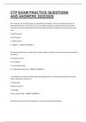
STRESSES
TENSILE
STRENGTH
BEAM
MOMENTS
• Load
per
cross
sectional
area.
• Even
more
stretching
after
the
elastic
limit
• Moment
=
Force
x
Distance
will
cause
the
material
to
neck
(get
thinner).
• Max
bending
moment
on
a
wing
occurs
at
• Tension
(tensile
stress)
–
EG/
fuselage
• Stress
increases
since
the
cross
sectional
the
root
due
to
furthest
distance
from
load.
• Compression
–
EG/
top
of
wing
area
reduces.
• Support
is
thicker
and
end
is
thinner
–
thus
• Shear
(cutting)
–
EG/
wing
root
bolts
• Just
before
failure,
the
material
has
saving
weight.
• Torsion
(twisting)
maximum
strength
per
unit
of
cross
• Bending
–
Compression
+
Tension
+
Shear
sectional
area.
This
is
the
tensile
strength.
• Buckling
–
Uneven
compressive
load
STRUTS
TYPES
OF
LOADS
BASIC
STRUCTURAL
MEMBERS
• Struts
are
designed
to
withstand
mainly
compressive
loads.
• Static
–
Continually
applied,
no
change.
• Tend
to
buckle
under
load
before
failure.
• Dynamic
–
Constantly
changes
BEAMS
• Normally
hollow.
• Cyclic
–
Continually
applied
and
removed.
• They
can
be
either
simply
supported
(both
ends)
or
be
cantilever
(one
end
only).
TIE
STRAINS
• They
are
subject
to
bending
with
one
side
in
tension
and
the
other
in
compression.
• Ties
are
designed
mainly
to
withstand
• Strain
is
deformation
due
to
stress.
• Beams
in
aircraft
are
usually
an
I
/
H
section
tensile
loads.
• Initially
proportional
to
stress
and
will
and
the
same
strength
as
a
whole
beam
is
• Normally
constructed
of
solid
rod
or
a
wire
return
to
original
shape.
possible
due
to
interaction
of
compression
of
relatively
small
diameter.
• Plastic
deformation
-‐
Once
elastic
limit
is
and
tension
(but
it
is
of
course
lighter).
exceeded,
stretching
will
continue
but
will
not
return
to
original.
, SYSTEMS
1
–
AIRCRAFT
STRUCTURES
&
AERODYNAMIC
LIMITATIONS
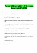
THE
FUSELAGE
SEMI
-‐
MONOCOQUE
FUSELAGE
FUSELAGE
TYPES
• Majority
of
stress
dissipated
by
internal
• Circular
THE
FUSELAGE
components
and
very
little
by
the
skin.
o Good
for
containing
hoop
stress
• Gives
a
strong,
relatively
light
structure
with
o Lowest
amount
of
skin
drag
for
volume
• Accommodates
crew
and
payload
lots
of
space.
o Bad
for
space
• Supports
other
components
of
the
aircraft.
• Longerons
–
Longitudinal
(Main
stresses)
• Rectangular
• Subject
to
a
number
of
stresses
in
flight:
• Frames
–
Vertical
(Stress
+
gives
rigidity)
o Max
use
of
space
o Nose
and
tail
droop
down
causing
• Stringers
–
Support
the
skin
o Bad
for
pressurization
tension
on
top
and
compression
• Bulkheads
–
Airtight
for
pressurisation
o Used
in
light
a/c
and
non
pressurised
underneath.
transporters.
o Compounded
by
tail
exerting
downforce
• Oval
o A380
Design
o Good
use
of
space
TRUSS
TYPE
FUSELAGE
o Best
compromise
for
pressurisation
o Requires
very
strong
floor
beams.
• Frame
supports
the
load,
skin
is
merely
to
o Double
bubble
section
can
be
used
to
cover
and
reduce
drag.
reduce
total
tension
on
each
frame.
• Longerons
run
longitudinally
and
provide
the
main
load
bearing.
• Supported
both
vertically,
horizontally
and
PRIMARY
VS
SECONDARY
STRUCTURE
diagonally
with
web
members
to
give
complete
rigidity.
• Primary
-‐
A
critical
load-‐bearing
structure.
• No
space
for
payload
so
mainly
on
light
• Secondary
–
Structural
elements
mainly
to
aircraft.
HOOP
STRESS
provide
enhanced
aerodynamics.
• Large
forces
which
push
the
fuselage
MONOCOQUE
FUSELAGE
outwards
as
a
result
of
pressurisation.
• Tension
in
frames.
• Skin
takes
all
the
load.
• Bending
in
longerons,
stringers
and
skin.
• No
internal
load
bearing
structure
although
former
rings
sometimes
fitted
to
give
shape.
• No
ability
to
add
doors
etc
otherwise
ability
of
skin
to
withstand
stress
is
destroyed.
, SYSTEMS
1
–
AIRCRAFT
STRUCTURES
&
AERODYNAMIC
LIMITATIONS
THE
WINGS
/
MAINPLANE
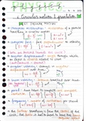
TORSION
BOX
THE
TAIL
• Supporting
the
twisting
motion
of
lift
of
the
THE
WINGS
wings.
TAIL
SECTION
• Links
the
spars,
skins
and
ribs.
• Semi-‐monocoque
design
• One
in
each
wing
plus
a
centre
spar
to
link
• Semi-‐monocoque
design
• Spars
–
Withstand
bending
and
torsional
the
two
wings.
loads
• Wing
torsion
can
result
from
positive
sweep
• Ribs
–
Gives
shape.
Holes
make
it
stronger
and
lighter.
• Stringers
–
Support
the
skin.
• Centre
spar
can
also
be
included
to
supported
undercarriage
etc.
SANDWICH
TYPE
CONSTRUCTION
HONEYCOMB
CONSTRUCTION
, SYSTEMS
1
–
AIRCRAFT
STRUCTURES
&
AERODYNAMIC
LIMITATIONS
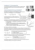
WING
BENDING
ON
GROUND
AIRCRAFT
STRUCTURAL
MATERIALS
ATTACHMENT
METHODS
• Wings
and
undercarriage
on
ground
are
• Aluminum
Alloy
• Riveting
subject
to
heavy
loads
so
the
Maximum
o Raw
aluminum
lacks
strength
+
rigidity
o Can
be
flush
or
round
headed
Ramp
Mass
is
set
to
limit
stress.
o Mixed
with
4-‐6%
copper
=
Duralumin
o Flush
type
is
more
aerodynamic
but
o Good
conductor
and
improved
strength
more
expensive.
o Difficult
to
weld
&
good
thermal
o Cracks
can
originate
at
rivet
points.
WING
BENDING
IN
FLIGHT
conductivity
• Bolts
• Magnesium
Alloy
o Allows
for
separation
of
materials
when
• Lift
acts
to
bend
wings
upwards.
o Lightweight
but
lack
strength
and
are
required.
• Fuel
and
engines
help
to
reduce
bending.
brittle.
o Vibrations
can
cause
nuts
to
become
• The
greatest
bending
moment
at
the
wing
o Easily
moulded
into
complex
shapes
loose.
This
is
prevented
by
wire
locking.
root
occurs
with
high
fuselage
mass
and
o Used
in
gearbox
casing
and
wheel
rims
• Welding
zero
fuel
(wings
bending
up).
The
• Steel
o A
very
tough
bond
is
created.
maximum
zero
fuel
mass
is
therefore
set
o Bolts
etc
o Load
spread
over
a
large
area.
to
limit
stress.
o Carbon
added
to
improve
load
bearing
• Pinning
• The
leading
edge
is
subject
to
compression
o +
chromium
=
stainless
steel
o Good
for
attaching
components
that
then
tension
(from
root
to
tip)
• Titanium
experience
shear
stress.
o Very
resistance
to
high
temperatures
o Can
be
undone
at
a
later
date.
o Turbines
etc
• Adhesives
• Plastic
o Easy
to
use
and
can
bond
large
areas.
FUSELAGE
BENDING
IN
FLIGHT
o Easy
to
mould
but
has
poor
strength.
o Permanent
and
have
relatively
low
o Interiors
mechanical
strength.
• Bending
moment
around
fuselage
due
to
• Fibre
Reinforced
Plastics
(FRPs)
download
on
the
horizontal
stabiliser
to
o Layers
of
fibres
(glass,
Kevlar,
carbon)
counteract
the
lift-‐weight
couple.
provide
the
strength
and
the
filler
gives
the
stiffness.
o CFRP
=
Carbon
Fibre
o KFRP
=
Kevlar
o GFRP
=
Glass
1
–
AIRCRAFT
STRUCTURES
&
AERODYNAMIC
LIMITATIONS
STRESSES
TENSILE
STRENGTH
BEAM
MOMENTS
• Load
per
cross
sectional
area.
• Even
more
stretching
after
the
elastic
limit
• Moment
=
Force
x
Distance
will
cause
the
material
to
neck
(get
thinner).
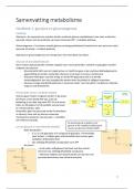
• Max
bending
moment
on
a
wing
occurs
at
• Tension
(tensile
stress)
–
EG/
fuselage
• Stress
increases
since
the
cross
sectional
the
root
due
to
furthest
distance
from
load.
• Compression
–
EG/
top
of
wing
area
reduces.
• Support
is
thicker
and
end
is
thinner
–
thus
• Shear
(cutting)
–
EG/
wing
root
bolts
• Just
before
failure,
the
material
has
saving
weight.
• Torsion
(twisting)
maximum
strength
per
unit
of
cross
• Bending
–
Compression
+
Tension
+
Shear
sectional
area.
This
is
the
tensile
strength.
• Buckling
–
Uneven
compressive
load
STRUTS
TYPES
OF
LOADS
BASIC
STRUCTURAL
MEMBERS
• Struts
are
designed
to
withstand
mainly
compressive
loads.
• Static
–
Continually
applied,
no
change.
• Tend
to
buckle
under
load
before
failure.
• Dynamic
–
Constantly
changes
BEAMS
• Normally
hollow.
• Cyclic
–
Continually
applied
and
removed.
• They
can
be
either
simply
supported
(both
ends)
or
be
cantilever
(one
end
only).
TIE
STRAINS
• They
are
subject
to
bending
with
one
side
in
tension
and
the
other
in
compression.
• Ties
are
designed
mainly
to
withstand
• Strain
is
deformation
due
to
stress.
• Beams
in
aircraft
are
usually
an
I
/
H
section
tensile
loads.
• Initially
proportional
to
stress
and
will
and
the
same
strength
as
a
whole
beam
is
• Normally
constructed
of
solid
rod
or
a
wire
return
to
original
shape.
possible
due
to
interaction
of
compression
of
relatively
small
diameter.
• Plastic
deformation
-‐
Once
elastic
limit
is
and
tension
(but
it
is
of
course
lighter).
exceeded,
stretching
will
continue
but
will
not
return
to
original.
, SYSTEMS
1
–
AIRCRAFT
STRUCTURES
&
AERODYNAMIC
LIMITATIONS
THE
FUSELAGE
SEMI
-‐
MONOCOQUE
FUSELAGE
FUSELAGE
TYPES
• Majority
of
stress
dissipated
by
internal
• Circular
THE
FUSELAGE
components
and
very
little
by
the
skin.
o Good
for
containing
hoop
stress
• Gives
a
strong,
relatively
light
structure
with
o Lowest
amount
of
skin
drag
for
volume
• Accommodates
crew
and
payload
lots
of
space.
o Bad
for
space
• Supports
other
components
of
the
aircraft.
• Longerons
–
Longitudinal
(Main
stresses)
• Rectangular
• Subject
to
a
number
of
stresses
in
flight:
• Frames
–
Vertical
(Stress
+
gives
rigidity)
o Max
use
of
space
o Nose
and
tail
droop
down
causing
• Stringers
–
Support
the
skin
o Bad
for
pressurization
tension
on
top
and
compression
• Bulkheads
–
Airtight
for
pressurisation
o Used
in
light
a/c
and
non
pressurised
underneath.
transporters.
o Compounded
by
tail
exerting
downforce
• Oval
o A380
Design
o Good
use
of
space
TRUSS
TYPE
FUSELAGE
o Best
compromise
for
pressurisation
o Requires
very
strong
floor
beams.
• Frame
supports
the
load,
skin
is
merely
to
o Double
bubble
section
can
be
used
to
cover
and
reduce
drag.
reduce
total
tension
on
each
frame.
• Longerons
run
longitudinally
and
provide
the
main
load
bearing.
• Supported
both
vertically,
horizontally
and
PRIMARY
VS
SECONDARY
STRUCTURE
diagonally
with
web
members
to
give
complete
rigidity.
• Primary
-‐
A
critical
load-‐bearing
structure.
• No
space
for
payload
so
mainly
on
light
• Secondary
–
Structural
elements
mainly
to
aircraft.
HOOP
STRESS
provide
enhanced
aerodynamics.
• Large
forces
which
push
the
fuselage
MONOCOQUE
FUSELAGE
outwards
as
a
result
of
pressurisation.
• Tension
in
frames.
• Skin
takes
all
the
load.
• Bending
in
longerons,
stringers
and
skin.
• No
internal
load
bearing
structure
although
former
rings
sometimes
fitted
to
give
shape.
• No
ability
to
add
doors
etc
otherwise
ability
of
skin
to
withstand
stress
is
destroyed.
, SYSTEMS
1
–
AIRCRAFT
STRUCTURES
&
AERODYNAMIC
LIMITATIONS
THE
WINGS
/
MAINPLANE
TORSION
BOX
THE
TAIL
• Supporting
the
twisting
motion
of
lift
of
the
THE
WINGS
wings.
TAIL
SECTION
• Links
the
spars,
skins
and
ribs.
• Semi-‐monocoque
design
• One
in
each
wing
plus
a
centre
spar
to
link
• Semi-‐monocoque
design
• Spars
–
Withstand
bending
and
torsional
the
two
wings.
loads
• Wing
torsion
can
result
from
positive
sweep
• Ribs
–
Gives
shape.
Holes
make
it
stronger
and
lighter.
• Stringers
–
Support
the
skin.
• Centre
spar
can
also
be
included
to
supported
undercarriage
etc.
SANDWICH
TYPE
CONSTRUCTION
HONEYCOMB
CONSTRUCTION
, SYSTEMS
1
–
AIRCRAFT
STRUCTURES
&
AERODYNAMIC
LIMITATIONS
WING
BENDING
ON
GROUND
AIRCRAFT
STRUCTURAL
MATERIALS
ATTACHMENT
METHODS
• Wings
and
undercarriage
on
ground
are
• Aluminum
Alloy
• Riveting
subject
to
heavy
loads
so
the
Maximum
o Raw
aluminum
lacks
strength
+
rigidity
o Can
be
flush
or
round
headed
Ramp
Mass
is
set
to
limit
stress.
o Mixed
with
4-‐6%
copper
=
Duralumin
o Flush
type
is
more
aerodynamic
but
o Good
conductor
and
improved
strength
more
expensive.
o Difficult
to
weld
&
good
thermal
o Cracks
can
originate
at
rivet
points.
WING
BENDING
IN
FLIGHT
conductivity
• Bolts
• Magnesium
Alloy
o Allows
for
separation
of
materials
when
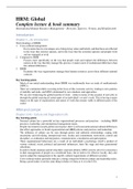
• Lift
acts
to
bend
wings
upwards.
o Lightweight
but
lack
strength
and
are
required.
• Fuel
and
engines
help
to
reduce
bending.
brittle.
o Vibrations
can
cause
nuts
to
become
• The
greatest
bending
moment
at
the
wing
o Easily
moulded
into
complex
shapes
loose.
This
is
prevented
by
wire
locking.
root
occurs
with
high
fuselage
mass
and
o Used
in
gearbox
casing
and
wheel
rims
• Welding
zero
fuel
(wings
bending
up).
The
• Steel
o A
very
tough
bond
is
created.
maximum
zero
fuel
mass
is
therefore
set
o Bolts
etc
o Load
spread
over
a
large
area.
to
limit
stress.
o Carbon
added
to
improve
load
bearing
• Pinning
• The
leading
edge
is
subject
to
compression
o +
chromium
=
stainless
steel
o Good
for
attaching
components
that
then
tension
(from
root
to
tip)
• Titanium
experience
shear
stress.
o Very
resistance
to
high
temperatures
o Can
be
undone
at
a
later
date.
o Turbines
etc
• Adhesives
• Plastic
o Easy
to
use
and
can
bond
large
areas.
FUSELAGE
BENDING
IN
FLIGHT
o Easy
to
mould
but
has
poor
strength.
o Permanent
and
have
relatively
low
o Interiors
mechanical
strength.
• Bending
moment
around
fuselage
due
to
• Fibre
Reinforced
Plastics
(FRPs)
download
on
the
horizontal
stabiliser
to
o Layers
of
fibres
(glass,
Kevlar,
carbon)
counteract
the
lift-‐weight
couple.
provide
the
strength
and
the
filler
gives
the
stiffness.
o CFRP
=
Carbon
Fibre
o KFRP
=
Kevlar
o GFRP
=
Glass