Chapter 4 Circuit Simplification
4.1 Thevenin’s Equivalent Circuit IL
Rsrc
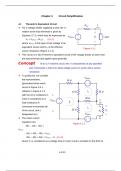
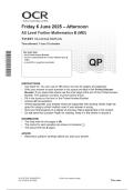
For a voltage divider supplying a load, the v-i
relation at the load terminals is given by +
Equation 2.7.5, which may be expressed as: V +
SRCoc VL Load
VL = VSRCoc – RsrcIL (4.1.1) –
–
where VSRCoc is the open-circuit voltage of an
equivalent source and Rsrc is the effective
Figure 4.1.1
source resistance (Figure 4.1.1).
This circuit is in fact Thevenin’s equivalent circuit of the voltage divider as seen from
the load terminals and applies quite generally.
Concept In an LTI resistive circuit, the v-i characteristic at any specified
pair of terminals is that of an ideal voltage source in series with a source
resistance.
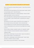
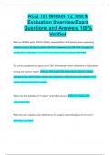
To justify this, we consider
VSRC2
the representative, 10
generalized three-mesh – +
circuit of Figure 3.6.1,
redrawn in Figure 4.1.2 10 I2 20
with the 10 resistance in
mesh 3 considered as a 30
VSRC1 + IL
I1
load resistance RL –
connected to terminals ab a +
IL
of the circuit, and I3 20 VL
RL
designated as IL. VSRC3 –
The mesh current + – b
equations are:
Figure 4.1.2
40I1 – 10I2 – 20IL =
VSRC1
-10I1 + 60I2 – 30IL = VSRC2
-20I1 – 30I2 + 50IL = VSRC3 – VL (4.1.2)
where VL is considered as a voltage drop in mesh 3 and is included on the RHS of
4-1/13
, the equation for this mesh.
Solving for IL and rearranging:
V L= [ 15 V SRC 1 +14 V SRC 2
23
+V SRC 3 − ]
430
23 L
I
(4.1.3)
Equation 4.1.3 is of the form of Eq 4.1.1, where VSRCoc equals the bracketed terms,
and Rsrc = 430/23. Since the circuit of Figure 4.1.2 is quite arbitrary, it is concluded
that the v-i relation for any given circuit at specified terminals ab is the same, in
general, as that of an ideal voltage source VSRCoc in series with a resistance Rsrc.
The VSRCoc-Rsrc circuit is the TEC of the given circuit at terminals ab and is the
simplest possible equivalent circuit, since it consists of just an ideal source and a
resistor. It is customary to refer to VSRCoc as the Thevenin voltage VTh, and to Rsrc as
the Thevenin resistance RTh.
VTh is determined as the open-circuit voltage at specified pair of terminals. If
terminals ab in Figure 4.1.2 are open circuited, IL = 0 and the mesh current equations
for the circuit become:
40I1 – 10I2 = VSRC1
-10I1 + 60I2 = VSRC2 (4.1.4)
0 .6 V SRC 1 +0 .1 V SRC 2 0 .1 V SRC 1 +0. 4 V SRC 2
I1= I2=
Solving for I1 and I2, 23 and 23 . From KVL,
VL = 30I2 + 20I1 + VSRC3. This gives: a
15 14
V Th = V SRC 1 + V SRC 2 +V SRC 3
23 23 (4.1.5) RTh
+
which is the open-circuit voltage determined above. VTh ISC
–
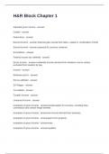
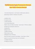
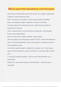
RTh can be determined in one of two ways. The first
follows from TEC (Figure 4.1.3a) when terminals ab
(a) b
V Th
RTh = RTh IT
are short circuited, which gives: I SC . a
In the above example, if terminals ab are short
circuited, VL = 0 and IL = ISC = +
VT
15 V SRC 1 +14 V SRC 2 +23 V SRC 3 –
=
430 . This gives
(b) b
430 Figure 4.1.3
RTh =
23 , as above.
4-2/13
4.1 Thevenin’s Equivalent Circuit IL
Rsrc
For a voltage divider supplying a load, the v-i
relation at the load terminals is given by +
Equation 2.7.5, which may be expressed as: V +
SRCoc VL Load
VL = VSRCoc – RsrcIL (4.1.1) –
–
where VSRCoc is the open-circuit voltage of an
equivalent source and Rsrc is the effective
Figure 4.1.1
source resistance (Figure 4.1.1).
This circuit is in fact Thevenin’s equivalent circuit of the voltage divider as seen from
the load terminals and applies quite generally.
Concept In an LTI resistive circuit, the v-i characteristic at any specified
pair of terminals is that of an ideal voltage source in series with a source
resistance.
To justify this, we consider
VSRC2
the representative, 10
generalized three-mesh – +
circuit of Figure 3.6.1,
redrawn in Figure 4.1.2 10 I2 20
with the 10 resistance in
mesh 3 considered as a 30
VSRC1 + IL
I1
load resistance RL –
connected to terminals ab a +
IL
of the circuit, and I3 20 VL
RL
designated as IL. VSRC3 –
The mesh current + – b
equations are:
Figure 4.1.2
40I1 – 10I2 – 20IL =
VSRC1
-10I1 + 60I2 – 30IL = VSRC2
-20I1 – 30I2 + 50IL = VSRC3 – VL (4.1.2)
where VL is considered as a voltage drop in mesh 3 and is included on the RHS of
4-1/13
, the equation for this mesh.
Solving for IL and rearranging:
V L= [ 15 V SRC 1 +14 V SRC 2
23
+V SRC 3 − ]
430
23 L
I
(4.1.3)
Equation 4.1.3 is of the form of Eq 4.1.1, where VSRCoc equals the bracketed terms,
and Rsrc = 430/23. Since the circuit of Figure 4.1.2 is quite arbitrary, it is concluded
that the v-i relation for any given circuit at specified terminals ab is the same, in
general, as that of an ideal voltage source VSRCoc in series with a resistance Rsrc.
The VSRCoc-Rsrc circuit is the TEC of the given circuit at terminals ab and is the
simplest possible equivalent circuit, since it consists of just an ideal source and a
resistor. It is customary to refer to VSRCoc as the Thevenin voltage VTh, and to Rsrc as
the Thevenin resistance RTh.
VTh is determined as the open-circuit voltage at specified pair of terminals. If
terminals ab in Figure 4.1.2 are open circuited, IL = 0 and the mesh current equations
for the circuit become:
40I1 – 10I2 = VSRC1
-10I1 + 60I2 = VSRC2 (4.1.4)
0 .6 V SRC 1 +0 .1 V SRC 2 0 .1 V SRC 1 +0. 4 V SRC 2
I1= I2=
Solving for I1 and I2, 23 and 23 . From KVL,
VL = 30I2 + 20I1 + VSRC3. This gives: a
15 14
V Th = V SRC 1 + V SRC 2 +V SRC 3
23 23 (4.1.5) RTh
+
which is the open-circuit voltage determined above. VTh ISC
–
RTh can be determined in one of two ways. The first
follows from TEC (Figure 4.1.3a) when terminals ab
(a) b
V Th
RTh = RTh IT
are short circuited, which gives: I SC . a
In the above example, if terminals ab are short
circuited, VL = 0 and IL = ISC = +
VT
15 V SRC 1 +14 V SRC 2 +23 V SRC 3 –
=
430 . This gives
(b) b
430 Figure 4.1.3
RTh =
23 , as above.
4-2/13