ENG 1450 Introduction to Electrical and computer Engineering
Lab 10
Optical Loading of a Shift Register, and Packet Identification
Name: _______________________________
Student Number: _______________________________
Lab Section: _______________________________
Instructor: _______________________________
Date: _______________________________
Build Quality (F / W / O) _________ _________________________
TA signature
Did students clean-up after the lab? _________________________
TA signature
ENG 1450 - Lab 10 Summer 2022-v1 Page 1
, Background & Time Saving Advice:
Today’s lab has two parts:
Part A: You will build a circuit to load data into an 8-bit shift register using an optical input.
Part B: The 8-bit data on the shift register has two parts. A 4-bit address packet and a 4-bit
data packet. You will build two combinational logic circuits to analyze the data.
**** You may want to divide your group into 2, with each sub-group building one of the 2
parts. You have 2 projects boards available to enable you to do this.
Part A: Shift Register with Optical Data Input
You will use an 8-bit shift register today as a memory storage element. You will transmit the
data to the shift register optically. This concept is similar to a fibre optic communication system.
The shift register you will use to day is the 74HC164 serial in - parallel out shift register. The
term “serial in” means it has 1 input wire to load the data. The term “parallel out” means it has 8
output lines (one for each bit in the register), allowing you to easily see the value of each of the 8
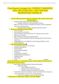
bits. The pin-out for the 74HC164 shift register is shown in Figure 1.
Figure 1: Pin-out schematic for the 8-bit 74HC164 serial in - parallel out shift register chip.
Make the following connections to wire the shift register. ** Neat wiring is very important. **
For power connect 5 V to pin 14 and 0 V to pin 7.
Connect pin 2 and pin 9 to 5 V.
Pins 3 - 6 and 10 - 13 are the 8 memory bits of the register, designated QA to QH .
Pin 1 is the data input (A input) and is used to input data to the shift register.
Pin 8 is the clock (CLK). It is used to synchronize data movement in the shift register,
and between the register’s various memory bits QA to QH .
ENG 1450 - Lab 10 Summer 2022-v1 Page 2
Lab 10
Optical Loading of a Shift Register, and Packet Identification
Name: _______________________________
Student Number: _______________________________
Lab Section: _______________________________
Instructor: _______________________________
Date: _______________________________
Build Quality (F / W / O) _________ _________________________
TA signature
Did students clean-up after the lab? _________________________
TA signature
ENG 1450 - Lab 10 Summer 2022-v1 Page 1
, Background & Time Saving Advice:
Today’s lab has two parts:
Part A: You will build a circuit to load data into an 8-bit shift register using an optical input.
Part B: The 8-bit data on the shift register has two parts. A 4-bit address packet and a 4-bit
data packet. You will build two combinational logic circuits to analyze the data.
**** You may want to divide your group into 2, with each sub-group building one of the 2
parts. You have 2 projects boards available to enable you to do this.
Part A: Shift Register with Optical Data Input
You will use an 8-bit shift register today as a memory storage element. You will transmit the
data to the shift register optically. This concept is similar to a fibre optic communication system.
The shift register you will use to day is the 74HC164 serial in - parallel out shift register. The
term “serial in” means it has 1 input wire to load the data. The term “parallel out” means it has 8
output lines (one for each bit in the register), allowing you to easily see the value of each of the 8
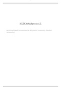
bits. The pin-out for the 74HC164 shift register is shown in Figure 1.
Figure 1: Pin-out schematic for the 8-bit 74HC164 serial in - parallel out shift register chip.
Make the following connections to wire the shift register. ** Neat wiring is very important. **
For power connect 5 V to pin 14 and 0 V to pin 7.
Connect pin 2 and pin 9 to 5 V.
Pins 3 - 6 and 10 - 13 are the 8 memory bits of the register, designated QA to QH .
Pin 1 is the data input (A input) and is used to input data to the shift register.
Pin 8 is the clock (CLK). It is used to synchronize data movement in the shift register,
and between the register’s various memory bits QA to QH .
ENG 1450 - Lab 10 Summer 2022-v1 Page 2