ENG 1450 Introduction to Electrical and computer Engineering
Lab 8
Resistor-Capacitor Filter, AM Receiver
Name: _______________________________
Student Number: _______________________________
Lab Section: _______________________________
Instructor: _______________________________
Date: _______________________________
Did students clean-up after the lab? _________________________
TA signature
ENG 1450 - Lab 8 November 7, 2016-v1 Page 1
, Part A: Resistor-Capacitor Filter
Use two metal plates and a piece of paper separating them to build a parallel plate capacitor.
You are using the capacitor to build a low pass filter.
Note: Make sure the two metal plates are pressing firmly against the paper separating them, so
that there is no air gap.
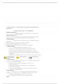
Figure 1 shows the circuit of a low pass filter. Build the circuit with the parallel plate capacitor
and a 10 kΩ resistor.
Figure 1: Low pass filter.
Apply a 1 kHz sinusoidal signal to your circuit (this is the voltage Vin), with an amplitude of 5 V.
1. In Table 1, record the value of Vout as you increase the frequency to 20 kHz. In Table 2,
record the value of Vout as you increase the frequency from 20 kHz to 100 kHz.
Table 1: Values of frequency and Vout
Frequency
1 kHz 20 kHz
(Hz)
Vout (V)
Table 2: Values of frequency and Vout
Frequency
20 kHz 100 kHz
(Hz)
Vout (V)
ENG 1450 - Lab 8 November 7, 2016-v1 Page 2
Lab 8
Resistor-Capacitor Filter, AM Receiver
Name: _______________________________
Student Number: _______________________________
Lab Section: _______________________________
Instructor: _______________________________
Date: _______________________________
Did students clean-up after the lab? _________________________
TA signature
ENG 1450 - Lab 8 November 7, 2016-v1 Page 1
, Part A: Resistor-Capacitor Filter
Use two metal plates and a piece of paper separating them to build a parallel plate capacitor.
You are using the capacitor to build a low pass filter.
Note: Make sure the two metal plates are pressing firmly against the paper separating them, so
that there is no air gap.
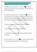
Figure 1 shows the circuit of a low pass filter. Build the circuit with the parallel plate capacitor
and a 10 kΩ resistor.
Figure 1: Low pass filter.
Apply a 1 kHz sinusoidal signal to your circuit (this is the voltage Vin), with an amplitude of 5 V.
1. In Table 1, record the value of Vout as you increase the frequency to 20 kHz. In Table 2,
record the value of Vout as you increase the frequency from 20 kHz to 100 kHz.
Table 1: Values of frequency and Vout
Frequency
1 kHz 20 kHz
(Hz)
Vout (V)
Table 2: Values of frequency and Vout
Frequency
20 kHz 100 kHz
(Hz)
Vout (V)
ENG 1450 - Lab 8 November 7, 2016-v1 Page 2