General Information 1
Care & Safety 2
R
Routine Maintenance 3
Attachments A
Service Body & Framework
B
Manual Electrics C
JS70
Hydraulics E
from machine no. 695501
Transmission F
Brakes G
PUBLISHED BY THE
TECHNICAL PUBLICATIONS DEPARTMENT
OF JCB SERVICE: ©
ROCESTER, STAFFORDSHIRE, ST14 5LS,
ENGLAND
Track & Running Gear J
Tel. ROCESTER (01889) 590312
PRINTED IN ENGLAND
Publication No. 9803/6020
Issue 0
Engine K
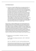
,Introduction
This publication is designed for the benefit of JCB Distributor Service Engineers who are receiving, or have received, training
by JCB Technical Training Department.
These personnel should have a sound knowledge of workshop practice, safety procedures, and general techniques associated
with the maintenance and repair of hydraulic earthmoving equipment.
Renewal of oil seals, gaskets, etc., and any component showing obvious signs of wear or damage is expected as a matter of
course. It is expected that components will be cleaned and lubricated where appropriate, and that any opened hose or pipe
connections will be blanked to prevent excessive loss of hydraulic fluid and ingress of dirt. Finally, please remember above all
else SAFETY MUST COME FIRST!
The manual is compiled in sections, the first three are numbered and contain information as follows:
1 = General Information - includes torque settings and service tools.
2 = Care & Safety - includes warnings and cautions pertinent to aspects of workshop procedures etc.
3 = Routine Maintenance - includes service schedules and recommended lubricants for the whole machine.
The remaining sections are alphabetically coded and deal with Dismantling, Overhaul etc. of specific components, for
example:
A = Attachments
B = Body & Framework ...etc
The page numbering in each alphabetically coded section is not continuous. This allows for the insertion of new items in later
issues of the manual.
Section contents, technical data, circuit descriptions, operation descriptions etc. are inserted at the beginning of each
alphabetically coded section.
All sections are listed on the front cover; tabbed divider cards align directly with individual sections on the front cover for rapid
reference.
Where a torque setting is given as a single figure it may be varied by plus or minus 3%. Torque figures indicated are for dry
threads, hence for lubricated threads may be reduced by one third.
‘Left Hand’ and ‘Right Hand’ are as viewed from the rear of the machine facing forwards.
Note: In this manual the term ‘swing’ may sometimes be used in place of ‘slew’ and the term ‘arm’ may sometimes be used in
place of ‘dipper’.
9803/6020 Issue 1
,Section 1 General Information Section 1
i i
Contents Page No.
Bolt and Nut Torque Specifications 1-1
General Torque Settings 1-2
Service Tools
Section C - Electrics 4-1
Section E - Hydraulics 5-1
Section F - Transmission 6-1
Sealing and Retaining Compounds 7-1
9803/6020 Issue 1
, Section 1 General Information Section 1
1-1 Bolt and Nut Torque Specifications 1-1
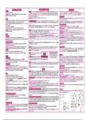
Bolt and Nut Torque Specifications
Tighten the bolts and nuts according to the table. Before and after daily work, check the bolts and nuts for looseness and for
those missing. Tighten if loose and renew if missing.
Tighten the bolts and nuts after the first 50 hours of the running-in stage and every 250 hours thereafter.
Torque Tightening Table
No Tightening Point Bolt Diameter Wrench Tightening Torque
mm Nm kgf m lbf ft
1† Travel Motor M16 24 268~312 27.2~31.8 197~230
2† Drive Sprocket M14 22 173~202 17.6~20.6 128~149
3† Idler Wheel M10 17 63~73 6.9~7.4 46~54
4† Upper (Carrier) Roller M16 24 267~312 27.2~31.8 197~230
5† Lower (Track) Roller M12 19 109~127 11~13 80~94
6† Grease Cylinder M12 19 109~127 11~13 80~94
7† Track Guard M12 19 109~127 11~13 80~94
8 Shoe Bolt U1/2 - 38 19 196~235 20~24 145~173
9† Counterweight M24 36 660~770 67.3~78.5 487~568
10† Turntable Bearing (Undercarriage) M16 24 252~283 25.7~28.9 186~209
11† Turntable Bearing (Slew Frame) M16 24 252~283 25.7~28.9 186~209
12† Slew Equipment M16 24 273~318 27.8~32.4 201~235
13† Engine (Engine Mount) M16 24 167~216 17~22 123~159
14† Engine Bracket M10/M16 17/24 65~75/167~216 6.6~7.7/17~22 48~55/123~159
15 Radiator M10 17 30~35 3.1~3.6 22~26
16† Hydraulic Pump M10/M12 17/19 63~73/109~127 6.4~7.4/11~13 46~54/80~94
17† Hydraulic Oil Tank M16 24 160~172 16.3~17.5 118~127
18† Fuel Tank M16 24 160~172 16.3~17.5 118~127
19† Control Valve M12 19 53~65 5.4~6.6 39~48
20† Rotary Coupling M10 17 63~73 6.4~7.4 46~54
21 Cab M16 24 79~88 8~9 58~65
22 Battery M10 17 20~30 2~3 15~22
Note: Use JCB Threadlocker and Sealer (High Strength) on those marked † and tighten to the torque listed in the above
table.
9803/6020 Issue 1
Care & Safety 2
R
Routine Maintenance 3
Attachments A
Service Body & Framework
B
Manual Electrics C
JS70
Hydraulics E
from machine no. 695501
Transmission F
Brakes G
PUBLISHED BY THE
TECHNICAL PUBLICATIONS DEPARTMENT
OF JCB SERVICE: ©
ROCESTER, STAFFORDSHIRE, ST14 5LS,
ENGLAND
Track & Running Gear J
Tel. ROCESTER (01889) 590312
PRINTED IN ENGLAND
Publication No. 9803/6020
Issue 0
Engine K
,Introduction
This publication is designed for the benefit of JCB Distributor Service Engineers who are receiving, or have received, training
by JCB Technical Training Department.
These personnel should have a sound knowledge of workshop practice, safety procedures, and general techniques associated
with the maintenance and repair of hydraulic earthmoving equipment.
Renewal of oil seals, gaskets, etc., and any component showing obvious signs of wear or damage is expected as a matter of
course. It is expected that components will be cleaned and lubricated where appropriate, and that any opened hose or pipe
connections will be blanked to prevent excessive loss of hydraulic fluid and ingress of dirt. Finally, please remember above all
else SAFETY MUST COME FIRST!
The manual is compiled in sections, the first three are numbered and contain information as follows:
1 = General Information - includes torque settings and service tools.
2 = Care & Safety - includes warnings and cautions pertinent to aspects of workshop procedures etc.
3 = Routine Maintenance - includes service schedules and recommended lubricants for the whole machine.
The remaining sections are alphabetically coded and deal with Dismantling, Overhaul etc. of specific components, for
example:
A = Attachments
B = Body & Framework ...etc
The page numbering in each alphabetically coded section is not continuous. This allows for the insertion of new items in later
issues of the manual.
Section contents, technical data, circuit descriptions, operation descriptions etc. are inserted at the beginning of each
alphabetically coded section.
All sections are listed on the front cover; tabbed divider cards align directly with individual sections on the front cover for rapid
reference.
Where a torque setting is given as a single figure it may be varied by plus or minus 3%. Torque figures indicated are for dry
threads, hence for lubricated threads may be reduced by one third.
‘Left Hand’ and ‘Right Hand’ are as viewed from the rear of the machine facing forwards.
Note: In this manual the term ‘swing’ may sometimes be used in place of ‘slew’ and the term ‘arm’ may sometimes be used in
place of ‘dipper’.
9803/6020 Issue 1
,Section 1 General Information Section 1
i i
Contents Page No.
Bolt and Nut Torque Specifications 1-1
General Torque Settings 1-2
Service Tools
Section C - Electrics 4-1
Section E - Hydraulics 5-1
Section F - Transmission 6-1
Sealing and Retaining Compounds 7-1
9803/6020 Issue 1
, Section 1 General Information Section 1
1-1 Bolt and Nut Torque Specifications 1-1
Bolt and Nut Torque Specifications
Tighten the bolts and nuts according to the table. Before and after daily work, check the bolts and nuts for looseness and for
those missing. Tighten if loose and renew if missing.
Tighten the bolts and nuts after the first 50 hours of the running-in stage and every 250 hours thereafter.
Torque Tightening Table
No Tightening Point Bolt Diameter Wrench Tightening Torque
mm Nm kgf m lbf ft
1† Travel Motor M16 24 268~312 27.2~31.8 197~230
2† Drive Sprocket M14 22 173~202 17.6~20.6 128~149
3† Idler Wheel M10 17 63~73 6.9~7.4 46~54
4† Upper (Carrier) Roller M16 24 267~312 27.2~31.8 197~230
5† Lower (Track) Roller M12 19 109~127 11~13 80~94
6† Grease Cylinder M12 19 109~127 11~13 80~94
7† Track Guard M12 19 109~127 11~13 80~94
8 Shoe Bolt U1/2 - 38 19 196~235 20~24 145~173
9† Counterweight M24 36 660~770 67.3~78.5 487~568
10† Turntable Bearing (Undercarriage) M16 24 252~283 25.7~28.9 186~209
11† Turntable Bearing (Slew Frame) M16 24 252~283 25.7~28.9 186~209
12† Slew Equipment M16 24 273~318 27.8~32.4 201~235
13† Engine (Engine Mount) M16 24 167~216 17~22 123~159
14† Engine Bracket M10/M16 17/24 65~75/167~216 6.6~7.7/17~22 48~55/123~159
15 Radiator M10 17 30~35 3.1~3.6 22~26
16† Hydraulic Pump M10/M12 17/19 63~73/109~127 6.4~7.4/11~13 46~54/80~94
17† Hydraulic Oil Tank M16 24 160~172 16.3~17.5 118~127
18† Fuel Tank M16 24 160~172 16.3~17.5 118~127
19† Control Valve M12 19 53~65 5.4~6.6 39~48
20† Rotary Coupling M10 17 63~73 6.4~7.4 46~54
21 Cab M16 24 79~88 8~9 58~65
22 Battery M10 17 20~30 2~3 15~22
Note: Use JCB Threadlocker and Sealer (High Strength) on those marked † and tighten to the torque listed in the above
table.
9803/6020 Issue 1