Unit 2: Communications for Engineering Technicians
Assignment 1: Communicating Technical Information (P1, P2 and P3)
P1
To achieve this criteria, I will interpret two different types of engineering drawing. The
two drawing that were given to me are isometric and orthographic projection.
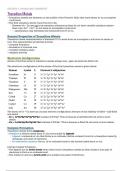
The first drawing is of a G Clamp assembly drawing, which I have interpret below;
Extracting information from the G Clamp assembly drawing, complete the parts table
below by adding the part names and the quantity required for each part
Item Name Quantity
1 G - Clamp Body 1
2 Clamp handle end 1
3 Anvil 1
4 Clamp thread foot 1
5 Tommy bar 1
6 Tommy bar end cap 2
7 Threaded bar 1
What is the drawing number for the G clamp assembly drawing
GC-ASSY001
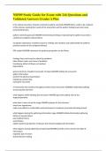
Dimension the rectangle below to show the minimum size of material blank required in
order to manufacture the G clamp body
75 X 50 mm
Explain why it is necessary to create two datum edges( datum A & datum B) in order to
accurately mark out the G clamp body.
Because it helps define the shape, size and feature on an object. It is used to create a reference
point for measurement, which is very important for accuracy.
What is the overall finished length and width of the G clamp body part.
75 X 50 mm
What is the tolerance given on the length and width dimensions? Explain what this
means?
Both the length and the width of the G clamp body has a tolerance of -0.25 and +0.00. This
means that the the length and width can be made up to 0.25mm smaller than the original size,
without affecting the overall performance of the product.
Riversan Thapa
Assignment 1: Communicating Technical Information (P1, P2 and P3)
P1
To achieve this criteria, I will interpret two different types of engineering drawing. The
two drawing that were given to me are isometric and orthographic projection.
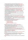
The first drawing is of a G Clamp assembly drawing, which I have interpret below;
Extracting information from the G Clamp assembly drawing, complete the parts table
below by adding the part names and the quantity required for each part
Item Name Quantity
1 G - Clamp Body 1
2 Clamp handle end 1
3 Anvil 1
4 Clamp thread foot 1
5 Tommy bar 1
6 Tommy bar end cap 2
7 Threaded bar 1
What is the drawing number for the G clamp assembly drawing
GC-ASSY001
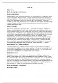
Dimension the rectangle below to show the minimum size of material blank required in
order to manufacture the G clamp body
75 X 50 mm
Explain why it is necessary to create two datum edges( datum A & datum B) in order to
accurately mark out the G clamp body.
Because it helps define the shape, size and feature on an object. It is used to create a reference
point for measurement, which is very important for accuracy.
What is the overall finished length and width of the G clamp body part.
75 X 50 mm
What is the tolerance given on the length and width dimensions? Explain what this
means?
Both the length and the width of the G clamp body has a tolerance of -0.25 and +0.00. This
means that the the length and width can be made up to 0.25mm smaller than the original size,
without affecting the overall performance of the product.
Riversan Thapa