Computer science—A Level—Topic 11 Boolean Algebra
Boolean logic Karnaugh Maps
Boolean logic is a form of algebra where all Karnaugh maps are used to simplify Boolean expressions, used to simplify real-world
values are reduced to either TRUE or FALSE logic requirements so that they can be implemented using the minimal number of physi-
named after George Boole. cal logic gates.
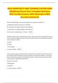
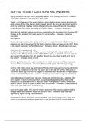
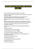
Here is a Two-input Karnaugh map representing two variables.
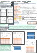
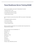
Logic gates and their corresponding truth tables
A Truth Table is a notation used in Boolean •It is already in its simplest state.
algebra for defining the output of a logic gate •There are two green boxes, one represents A and the other
or logic circuit for all possible combinations represents B therefore as they are separate, they are separate
of inputs. expressions therefore the OR (V) separates these expressions.
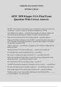
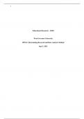
Here is a Three-input Karnaugh map representing three
variables.
•Box one represents just B because the variables A and C
change in this box where as B stays as one.
•Box two represents just C because the variables A and B
change in this box where as C stays the same therefore the
simplified expression is C V B.
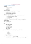
Here is a Four-input Karnaugh map representing four
variables.
•This expression does not get simplified because in each
box you keep either values therefore giving ¬C AND D OR
A AND B.
•It would still work the same way if it could be simplified.
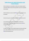
When drawing the boxes in the Karnaugh map, there are 8 rules to follow however the
unusual ones are:
•Boxes can overlap.
•Boxes of 2^n sizes.
What are the Boolean operators? •Smallest number of boxes.
•AND—Conjunction
•NOT –Negation How can Karnaugh maps be used to simplify Boolean expressions
•OR—Disjunction Karnaugh maps can simplify Boolean expressions by taking in two variables and showing the cells that are
•XOR –Exclusive / Disjunction true depending on the variable's state, this may allow us to simplify the Boolean expression to just a single
variable as shown above which reduces the electrical components in a circuit saving money and power.
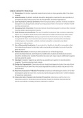
Logic gate diagrams Once you have constructed your Karnaugh map with all the boxes making sure you follow the rules then
for each box get each variable and if the digit stored in the variable's heading changes then you discard
A method of expressing Boole- that variable but if it doesn't change then you keep the variable and you do this on all the other boxes on
an Logic in a diagrammatic the Karnaugh map.
form using a set of standard
symbols representing the vari-
ous Logic Gates such as AND
NOT OR NAND etc.
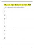
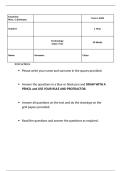
This expression would be:
F = (A XOR B) AND (NOT C)
This expression would be:
F = ¬A XOR (B OR C)
How do you translate a logic gate diagram
into its associated truth table and Boolean
expression and vice versa?
To construct a Truth table, you would create
a column for each of the inputs then listing
all the possible combinations by counting up This expression would be:
in binary. Additional columns are required F = (A OR B) AND (NOT C)
for the final and interim inputs.
To convert into a Boolean expression, start
by making it equal to the letter representing
the final output and use the correct symbols
for each Boolean notation.
Boolean logic Karnaugh Maps
Boolean logic is a form of algebra where all Karnaugh maps are used to simplify Boolean expressions, used to simplify real-world
values are reduced to either TRUE or FALSE logic requirements so that they can be implemented using the minimal number of physi-
named after George Boole. cal logic gates.
Here is a Two-input Karnaugh map representing two variables.
Logic gates and their corresponding truth tables
A Truth Table is a notation used in Boolean •It is already in its simplest state.
algebra for defining the output of a logic gate •There are two green boxes, one represents A and the other
or logic circuit for all possible combinations represents B therefore as they are separate, they are separate
of inputs. expressions therefore the OR (V) separates these expressions.
Here is a Three-input Karnaugh map representing three
variables.
•Box one represents just B because the variables A and C
change in this box where as B stays as one.
•Box two represents just C because the variables A and B
change in this box where as C stays the same therefore the
simplified expression is C V B.
Here is a Four-input Karnaugh map representing four
variables.
•This expression does not get simplified because in each
box you keep either values therefore giving ¬C AND D OR
A AND B.
•It would still work the same way if it could be simplified.
When drawing the boxes in the Karnaugh map, there are 8 rules to follow however the
unusual ones are:
•Boxes can overlap.
•Boxes of 2^n sizes.
What are the Boolean operators? •Smallest number of boxes.
•AND—Conjunction
•NOT –Negation How can Karnaugh maps be used to simplify Boolean expressions
•OR—Disjunction Karnaugh maps can simplify Boolean expressions by taking in two variables and showing the cells that are
•XOR –Exclusive / Disjunction true depending on the variable's state, this may allow us to simplify the Boolean expression to just a single
variable as shown above which reduces the electrical components in a circuit saving money and power.
Logic gate diagrams Once you have constructed your Karnaugh map with all the boxes making sure you follow the rules then
for each box get each variable and if the digit stored in the variable's heading changes then you discard
A method of expressing Boole- that variable but if it doesn't change then you keep the variable and you do this on all the other boxes on
an Logic in a diagrammatic the Karnaugh map.
form using a set of standard
symbols representing the vari-
ous Logic Gates such as AND
NOT OR NAND etc.
This expression would be:
F = (A XOR B) AND (NOT C)
This expression would be:
F = ¬A XOR (B OR C)
How do you translate a logic gate diagram
into its associated truth table and Boolean
expression and vice versa?
To construct a Truth table, you would create
a column for each of the inputs then listing
all the possible combinations by counting up This expression would be:
in binary. Additional columns are required F = (A OR B) AND (NOT C)
for the final and interim inputs.
To convert into a Boolean expression, start
by making it equal to the letter representing
the final output and use the correct symbols
for each Boolean notation.