Fluoroscopy Final exam Question with 100% correct
Answers 2024
How is fluoroscopy used in angiography?
To position the system for the recording of images of contrast material being injected via catheter
How is fluoroscopy used in angioplasty?
To provide imaging guidance for interventional procedures?
Three types of fluoroscopy cameras
analog vidicon, CCD or CMOS (Complementary metal-oxide semiconductor)
"Real time" imaging frame rate
30 fps, about the same as old analog TVs
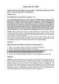
Fluoroscopic imaging chain diagram
Copper filtration is combined with (higher/lower) kVs for dose reduction in angiography
lower
,When would you use an attenuator wedge in a fluoroscopic system?
To reduce bright regions, such as those created in the pulmonary space between the heart and chest
wall
Dose difference per image between fluoroscopy and radiography
fluoroscopy: 9-17 nGy (1-2 uR) per image
radiography: 5-9 uGy (.6-1 mR) per image
Four principle components of an II
1. vacuum housing to keep air out and allow unimpeded e- flow
2. an input layer that converts the absorbed incident x-rays into light, which in turn releases e-
3. an e- optics system that accelerates and focuses the e- emitted by the input layer onto an output
layer
4. an output phosphor that concerts the accelerated e- into a visible light image
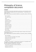
II Diagram
G1-3 are additional focusing electrodes
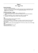
II Input Screen Diagram
The vacuum window of an II is typically made of what?
~1mm Al
, Why is the input surface of an II curved?
To withstand the force of air pressing against it (contains vacuum). A 35 cm FOV can withstand a ton
of atmospheric air pressure
What is the support layer of the II Input Screen?
Commonly 0.5 mm Al, supports the input phosphor and photo-cathode layers. The first component in
the electronic lens system, its curvature designed for accurate e- focusing
Most common material for II phosphor
CsI, can be formed into columnar "light pipes." As a result, the phosphor can be quite thick and still
produce high res. They are approx 400 um tall and 5 um wide and formed by vacuum deposition of CsI
onto substrate. They contain a trace amount of Na, causing them to emit blue light. The K-edges of Cs
(36 keV) and I (33 keV) are well positioned with respect to the fluoroscopic x-ray spectrum, which
contribute to high x-ray absorption efficiency
K-edge of cesium (CS)
36 keV
K-edge of Iodine (I)
33 keV
Photocathode of II
A thin layer of antimony and alkali metals (such as Sb2S3) that emits e- when struck by visible light
(10-20% conversion efficiency)
Answers 2024
How is fluoroscopy used in angiography?
To position the system for the recording of images of contrast material being injected via catheter
How is fluoroscopy used in angioplasty?
To provide imaging guidance for interventional procedures?
Three types of fluoroscopy cameras
analog vidicon, CCD or CMOS (Complementary metal-oxide semiconductor)
"Real time" imaging frame rate
30 fps, about the same as old analog TVs
Fluoroscopic imaging chain diagram
Copper filtration is combined with (higher/lower) kVs for dose reduction in angiography
lower
,When would you use an attenuator wedge in a fluoroscopic system?
To reduce bright regions, such as those created in the pulmonary space between the heart and chest
wall
Dose difference per image between fluoroscopy and radiography
fluoroscopy: 9-17 nGy (1-2 uR) per image
radiography: 5-9 uGy (.6-1 mR) per image
Four principle components of an II
1. vacuum housing to keep air out and allow unimpeded e- flow
2. an input layer that converts the absorbed incident x-rays into light, which in turn releases e-
3. an e- optics system that accelerates and focuses the e- emitted by the input layer onto an output
layer
4. an output phosphor that concerts the accelerated e- into a visible light image
II Diagram
G1-3 are additional focusing electrodes
II Input Screen Diagram
The vacuum window of an II is typically made of what?
~1mm Al
, Why is the input surface of an II curved?
To withstand the force of air pressing against it (contains vacuum). A 35 cm FOV can withstand a ton
of atmospheric air pressure
What is the support layer of the II Input Screen?
Commonly 0.5 mm Al, supports the input phosphor and photo-cathode layers. The first component in
the electronic lens system, its curvature designed for accurate e- focusing
Most common material for II phosphor
CsI, can be formed into columnar "light pipes." As a result, the phosphor can be quite thick and still
produce high res. They are approx 400 um tall and 5 um wide and formed by vacuum deposition of CsI
onto substrate. They contain a trace amount of Na, causing them to emit blue light. The K-edges of Cs
(36 keV) and I (33 keV) are well positioned with respect to the fluoroscopic x-ray spectrum, which
contribute to high x-ray absorption efficiency
K-edge of cesium (CS)
36 keV
K-edge of Iodine (I)
33 keV
Photocathode of II
A thin layer of antimony and alkali metals (such as Sb2S3) that emits e- when struck by visible light
(10-20% conversion efficiency)