ELEN7043: ADVANCED ELECTROMECHANICAL CONVERSION
Course Project: Modelling and Simulaton of A 400kW 4-Pole
Synchronous-Machine Intended To Be Mechanically Driven
With DC Motor And 4 Quadrant Drive Combinaton To Provide
Variable Speed
Candidate
Student Name
Student Number
XXXXXX
I hereby declare this is my own unaided work, submitted in partial fulfillment for the
degree in Master of Engineering in Electrical
Table of Contents
1. INTRODUCTION...................................................................................................................................3
,ELEN7043 Project: Modelling And Simulaton Of A 400kW 4-Pole Synchronous-Machine Intended To Be
Mechanically Driven With A DC Motor and 4 Quadrant Drive Combinaton To Provide Variable Speed
2. PROJECT SCOPE AND CONSTRAINTS...................................................................................................3
3. SYNCHRONOUS MACHINES DESIGN AND OPERATION........................................................................4
3.1 Synchronous Machines Structure......................................................................................................4
3.2 Excitaton System of a Synchronous Generator.................................................................................6
3.3 Operaton Principles of the Synchronous Machine...........................................................................7
3.4 Design Trade-ofs of Synchronous Machines...................................................................................10
4. CONTROLLING ELECTRICAL AND MECHANICAL EQUATION FORMULATION.....................................11
4.1 Assumpton for the Formulaton Equatons.....................................................................................12
4.2 The Electrical System Equatons......................................................................................................12
4.3 The Mechanical System Equatons..................................................................................................12
4.4 The Conical State Space Equatons..................................................................................................13
5. DETERMINATION OF THE MACHINE PARAMETERS...........................................................................13
5.1 Measuring Assumptons on the Laboratory Set-up.........................................................................14
5.2 Electrical Parameters Estmaton Procedure and Calculatons........................................................15
5.2.1 Stator Self Inductance () and Field Self Inductance ()...............................................................15
5.2.2 Stator and Rotor Mutual Inductance Measurements ()............................................................16
5.2.3 Coil Resistance Measurements ().............................................................................................17
5.2.4 Machine Motoring Inductance.................................................................................................18
5.3 Mechanical Parameters Estmaton Procedure and Calculatons....................................................18
5.3.1 Damping Coefcient.................................................................................................................18
5.3.2 Moment of Inerta....................................................................................................................19
6. MODELLING, SIMULATION AND RESULTS ANALYSIS.........................................................................20
6.1 Generator run-up with feld excitaton............................................................................................20
6.2 Generator run-up without feld excitaton......................................................................................22
7. CONCLUSION.....................................................................................................................................23
B.1.1. Measuring method..................................................................................................................28
B.1.2. Inductance Measurements......................................................................................................30
Page |2
XXXXXX
,ELEN7043 Project: Modelling And Simulaton Of A 400kW 4-Pole Synchronous-Machine Intended To Be
Mechanically Driven With A DC Motor and 4 Quadrant Drive Combinaton To Provide Variable Speed
1. INTRODUCTION
A synchronous machine is an alternatng current (AC) rotatng machine whose speed under steady state
conditon is proportonal to the frequency of the current in its armature. The magnetc feld created by
the armature currents rotates at the same speed as the feld created by the feld current on the rotor,
which is rotatng at synchronous speed and, a steady torque results.
The synchronous machines supplies power used by all sectors of modern societes: industrial,
commercial, agricultural and domestc. Synchronous machines commonly used as generators especially
for large power systems, such as turbine generators and hydroelectric generators in the grid power
supply. Since the reactve power generated by a synchronous machine can be adjusted by controlling
the magnitude of the rotor feld current, unloaded synchronous machine are also ofen installed in
power systems solely for power factors correcton or control of reactve power (KVAr) fow [1].
Synchronous machines are sometmes used in situatons where constant speed drive is required, as
synchronous motors, by controlling the frequency of excitaton as it is directly proportonal to the rotor
speed. With the power electronics variable voltage variable frequencies power supplies, synchronous
motors, especially those with permanent magnet motors are widely used for variable speed drives. If
the stator excitaton of a permanent magnet motor is controlled by its rotor positon such that the
stator feld is always 90° (electrical) ahead of the rotor, the motor performance can be very close to the
conventonal brushed dc motors, which is very favoured for variable drives. Then the rotor positon can
be either detected by using rotor positon sensors or deduced from the electromotve force ( emf in
voltage) in stator windings [1].
The determinaton of the parameters of synchronous machines has naturally been of interest to both
machine designers and plant operators, and the ultmate aim of the machine designer is the predicton
of the machine performance and therefore necessarily the machine parameters from design
informaton, confrmed by the results of the machine tests.
This project is meant as the culminaton of all methods covered in the course where by it intends to
combine modelling and simulaton aspects of a real system which includes formulaton of equatons
from frst principle, estmatng the relevant parameters, castng it all in the state space formulaton and
performing a computer simulaton of the system.
This project report is structured by providing the project scope and constraints in Secton 2, the
underlying principles of operaton of the synchronous machine and engineering design trade-of are
investgated in Secton 3. The controlling electrical and mechanical equatons are formulated in Secton
4 and the physical system parameters are estmated by measurements in the laboratory as prescribed
Secton 5. The formulaton will be then be simulated and analysed in Secton 6 for a run-up of the
synchronous machine with and without feld current. The results will be analysed and then project will
be concluded in Secton 7.
2. PROJECT SCOPE AND CONSTRAINTS
The project scope is as follows:
Page |3
XXXXXX
, ELEN7043 Project: Modelling And Simulaton Of A 400kW 4-Pole Synchronous-Machine Intended To Be
Mechanically Driven With A DC Motor and 4 Quadrant Drive Combinaton To Provide Variable Speed
Investgatng and understanding the operaton of the synchronous-machine, getng a good
grasp of the underlying principles of operaton and understanding the engineering trade-ofs
that has been made in the design.
Formulatng the controlling electrical and mechanical equatons for this device, using
appropriate measurements and assumptons, estmate the required parameters (of the physical
system) for the modelling equatons, critcally analyse assumptons and estmatons, re-
formulate modelling equatons into the canonical state-space format.
Estmatng the inductance of the machine in Excel and coding the system of equatons in
MatLab and simulate the generator run-up with and without feld excitaton.
Critcally analysing the results, comment on the accuracy and usability of the methods applied
and make recommendatons to increase accuracy of model and improve results as necessary.
The constraint for this project is the provided structure of a 400kW 4-pole synchronous-machine. The
machine is to be mechanically driven with a DC motor and 4 quadrant drive combinaton to provide
variable speed. It will be operated as a stand-alone generator with no grid synchronisaton in this
project.
3. SYNCHRONOUS MACHINES DESIGN AND OPERATION
3.1 Synchronous Machines Structure
This secton discusses the synchronous machines stator and rotor structure. The armature winding of a
conventonal synchronous machine is almost invariably on the stator and is usually a three phase
winding, composed of a cylindrical laminated core containing a set of slots. The winding is always
preferred to be connected in a star connecton and the neutral is connected to the ground [2].
The feld winding is usually on the rotor and excited by direct current (DC) or permanent magnets. In
older machines, the excitaton current was typically supplied through slip rings from a DC machine,
referred to as the exciter, which was ofen mounted on the same shaf as the synchronous machine. In
more modern systems, the excitaton is supplied from AC exciters and solid-state rectfers (either
simple diode bridges or phase-controlled rectfers) [1], [3]. The excitaton system will be further
discussed in secton 3.2.
There are two types of rotor structures which is a salient rotor and non-salient (round or cylindrical pole
rotor.
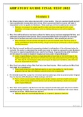
Figure 1 depicts the schematc diagram of a salient rotor synchronous machine and its armature
windings consists here of a single coil N turns, is indicated in cross secton by two coil side a and –a
placed diametrically opposite narrow slots on the inner periphery of the stator. A great many salient
synchronous machines have more than two poles, as depicted in Figure 2 shows a schematc form of a
four-pole salient synchronous machine, where by the feld coils are connected so that the poles are of
alternatve polarity. The armature winding now consists of two coils a1, -a1 and a2, -a2 connected in
series by their end connectons. The span of each coil is one wavelength of fux with the generated
voltage now goes through complete cycles per revoluton on the rotor. Then the frequency in hertz will
thus be twice the speed revoluton per second [3].
Salient-pole rotors are usually driven by low-speed hydraulic turbines and cylindrical rotors are driven
by high-speed steam turbines. Most hydraulic turbines have to turn at low speeds in order to extract the
Page |4
XXXXXX
Course Project: Modelling and Simulaton of A 400kW 4-Pole
Synchronous-Machine Intended To Be Mechanically Driven
With DC Motor And 4 Quadrant Drive Combinaton To Provide
Variable Speed
Candidate
Student Name
Student Number
XXXXXX
I hereby declare this is my own unaided work, submitted in partial fulfillment for the
degree in Master of Engineering in Electrical
Table of Contents
1. INTRODUCTION...................................................................................................................................3
,ELEN7043 Project: Modelling And Simulaton Of A 400kW 4-Pole Synchronous-Machine Intended To Be
Mechanically Driven With A DC Motor and 4 Quadrant Drive Combinaton To Provide Variable Speed
2. PROJECT SCOPE AND CONSTRAINTS...................................................................................................3
3. SYNCHRONOUS MACHINES DESIGN AND OPERATION........................................................................4
3.1 Synchronous Machines Structure......................................................................................................4
3.2 Excitaton System of a Synchronous Generator.................................................................................6
3.3 Operaton Principles of the Synchronous Machine...........................................................................7
3.4 Design Trade-ofs of Synchronous Machines...................................................................................10
4. CONTROLLING ELECTRICAL AND MECHANICAL EQUATION FORMULATION.....................................11
4.1 Assumpton for the Formulaton Equatons.....................................................................................12
4.2 The Electrical System Equatons......................................................................................................12
4.3 The Mechanical System Equatons..................................................................................................12
4.4 The Conical State Space Equatons..................................................................................................13
5. DETERMINATION OF THE MACHINE PARAMETERS...........................................................................13
5.1 Measuring Assumptons on the Laboratory Set-up.........................................................................14
5.2 Electrical Parameters Estmaton Procedure and Calculatons........................................................15
5.2.1 Stator Self Inductance () and Field Self Inductance ()...............................................................15
5.2.2 Stator and Rotor Mutual Inductance Measurements ()............................................................16
5.2.3 Coil Resistance Measurements ().............................................................................................17
5.2.4 Machine Motoring Inductance.................................................................................................18
5.3 Mechanical Parameters Estmaton Procedure and Calculatons....................................................18
5.3.1 Damping Coefcient.................................................................................................................18
5.3.2 Moment of Inerta....................................................................................................................19
6. MODELLING, SIMULATION AND RESULTS ANALYSIS.........................................................................20
6.1 Generator run-up with feld excitaton............................................................................................20
6.2 Generator run-up without feld excitaton......................................................................................22
7. CONCLUSION.....................................................................................................................................23
B.1.1. Measuring method..................................................................................................................28
B.1.2. Inductance Measurements......................................................................................................30
Page |2
XXXXXX
,ELEN7043 Project: Modelling And Simulaton Of A 400kW 4-Pole Synchronous-Machine Intended To Be
Mechanically Driven With A DC Motor and 4 Quadrant Drive Combinaton To Provide Variable Speed
1. INTRODUCTION
A synchronous machine is an alternatng current (AC) rotatng machine whose speed under steady state
conditon is proportonal to the frequency of the current in its armature. The magnetc feld created by
the armature currents rotates at the same speed as the feld created by the feld current on the rotor,
which is rotatng at synchronous speed and, a steady torque results.
The synchronous machines supplies power used by all sectors of modern societes: industrial,
commercial, agricultural and domestc. Synchronous machines commonly used as generators especially
for large power systems, such as turbine generators and hydroelectric generators in the grid power
supply. Since the reactve power generated by a synchronous machine can be adjusted by controlling
the magnitude of the rotor feld current, unloaded synchronous machine are also ofen installed in
power systems solely for power factors correcton or control of reactve power (KVAr) fow [1].
Synchronous machines are sometmes used in situatons where constant speed drive is required, as
synchronous motors, by controlling the frequency of excitaton as it is directly proportonal to the rotor
speed. With the power electronics variable voltage variable frequencies power supplies, synchronous
motors, especially those with permanent magnet motors are widely used for variable speed drives. If
the stator excitaton of a permanent magnet motor is controlled by its rotor positon such that the
stator feld is always 90° (electrical) ahead of the rotor, the motor performance can be very close to the
conventonal brushed dc motors, which is very favoured for variable drives. Then the rotor positon can
be either detected by using rotor positon sensors or deduced from the electromotve force ( emf in
voltage) in stator windings [1].
The determinaton of the parameters of synchronous machines has naturally been of interest to both
machine designers and plant operators, and the ultmate aim of the machine designer is the predicton
of the machine performance and therefore necessarily the machine parameters from design
informaton, confrmed by the results of the machine tests.
This project is meant as the culminaton of all methods covered in the course where by it intends to
combine modelling and simulaton aspects of a real system which includes formulaton of equatons
from frst principle, estmatng the relevant parameters, castng it all in the state space formulaton and
performing a computer simulaton of the system.
This project report is structured by providing the project scope and constraints in Secton 2, the
underlying principles of operaton of the synchronous machine and engineering design trade-of are
investgated in Secton 3. The controlling electrical and mechanical equatons are formulated in Secton
4 and the physical system parameters are estmated by measurements in the laboratory as prescribed
Secton 5. The formulaton will be then be simulated and analysed in Secton 6 for a run-up of the
synchronous machine with and without feld current. The results will be analysed and then project will
be concluded in Secton 7.
2. PROJECT SCOPE AND CONSTRAINTS
The project scope is as follows:
Page |3
XXXXXX
, ELEN7043 Project: Modelling And Simulaton Of A 400kW 4-Pole Synchronous-Machine Intended To Be
Mechanically Driven With A DC Motor and 4 Quadrant Drive Combinaton To Provide Variable Speed
Investgatng and understanding the operaton of the synchronous-machine, getng a good
grasp of the underlying principles of operaton and understanding the engineering trade-ofs
that has been made in the design.
Formulatng the controlling electrical and mechanical equatons for this device, using
appropriate measurements and assumptons, estmate the required parameters (of the physical
system) for the modelling equatons, critcally analyse assumptons and estmatons, re-
formulate modelling equatons into the canonical state-space format.
Estmatng the inductance of the machine in Excel and coding the system of equatons in
MatLab and simulate the generator run-up with and without feld excitaton.
Critcally analysing the results, comment on the accuracy and usability of the methods applied
and make recommendatons to increase accuracy of model and improve results as necessary.
The constraint for this project is the provided structure of a 400kW 4-pole synchronous-machine. The
machine is to be mechanically driven with a DC motor and 4 quadrant drive combinaton to provide
variable speed. It will be operated as a stand-alone generator with no grid synchronisaton in this
project.
3. SYNCHRONOUS MACHINES DESIGN AND OPERATION
3.1 Synchronous Machines Structure
This secton discusses the synchronous machines stator and rotor structure. The armature winding of a
conventonal synchronous machine is almost invariably on the stator and is usually a three phase
winding, composed of a cylindrical laminated core containing a set of slots. The winding is always
preferred to be connected in a star connecton and the neutral is connected to the ground [2].
The feld winding is usually on the rotor and excited by direct current (DC) or permanent magnets. In
older machines, the excitaton current was typically supplied through slip rings from a DC machine,
referred to as the exciter, which was ofen mounted on the same shaf as the synchronous machine. In
more modern systems, the excitaton is supplied from AC exciters and solid-state rectfers (either
simple diode bridges or phase-controlled rectfers) [1], [3]. The excitaton system will be further
discussed in secton 3.2.
There are two types of rotor structures which is a salient rotor and non-salient (round or cylindrical pole
rotor.
Figure 1 depicts the schematc diagram of a salient rotor synchronous machine and its armature
windings consists here of a single coil N turns, is indicated in cross secton by two coil side a and –a
placed diametrically opposite narrow slots on the inner periphery of the stator. A great many salient
synchronous machines have more than two poles, as depicted in Figure 2 shows a schematc form of a
four-pole salient synchronous machine, where by the feld coils are connected so that the poles are of
alternatve polarity. The armature winding now consists of two coils a1, -a1 and a2, -a2 connected in
series by their end connectons. The span of each coil is one wavelength of fux with the generated
voltage now goes through complete cycles per revoluton on the rotor. Then the frequency in hertz will
thus be twice the speed revoluton per second [3].
Salient-pole rotors are usually driven by low-speed hydraulic turbines and cylindrical rotors are driven
by high-speed steam turbines. Most hydraulic turbines have to turn at low speeds in order to extract the
Page |4
XXXXXX