SOLUTIONS MANUAL FOR
Understanding Structures:
An Introduction
to Structural
Analysis
by
Mete A. Sozen
Toshikatsu Ichinose
** Immediate Download
** Swift Response
** All Chapters included
75039_FM.indd 1 10/25/07 1:10:31
, 2007/10/25
Answers to Problems
P AB = 5 3
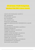
1-1. Equilibrium of forces at node A is shown graphically in Fig. F = 10
1-1. Because 5 3 ≈ 8.7 , No. 5 is correct.
P AC = 5
Fig. 1-1
1-2. Noting that (stress) = (axial force)/(cross-sectional area), the stresses of members AB and AC
are
PAB 5 3 PAC 5
σ AB = = (kN/mm 2 ) and σ AC = = (kN/mm 2 )
A 100 A 100
Because (strain) = (stress)/(Young’s modulus), strains in members AB and AC are
σ AB 5 3 σ AC 5
ε AB = = (No unit) and ε AC = = (No unit)
E 100 × 200 E 100 × 200
Recalling (deformation) = (strain)x(length), we have
5 3 5 3
eAB = ε AB × LAB = × 10, 000 = ≈ 4.3 ( mm )
100 × 200 2
5 5 3
eAC = ε AC × LAC = × 10, 000 3 = ≈ 4.3 ( mm )
100 × 200 2
No. 3 is correct.
1-3. Because the strength of the material is 200 N/mm2 and its cross-sectional area is 100 mm2, the
maximum possible axial force is 200 x 100 = 20 kN. On the other hand, the axial forces in members
AB and AC caused by an external force F are as follows (see Fig. 1-1).
394
, 2007/10/25
3 1
PAB = F PAC = F
2 2
Noting that PAB is larger than PAC, we can assume that the truss fails if PAB = 20 kN.
3 2
PAB = F = 20 leads to F = × 20 ≈ 23.1 (kN )
2 3
No. 4 is correct.
1-4. Equilibrium of the moments around support A leads to a reaction at support E expressed as
5
RE = × 20 = 5 ( N) .
20
Equilibrium of vertical forces leads to
RA = 20 − RE = 15 ( N) .
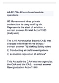
Equilibrium at joint A shown in Fig. 1-2a yields PAC = 15 kN, while equilibrium at joint E shown in
Fig. 1-2b yields PCE = 5 kN.
No. 1 is correct.
PAB PDE
PAB PDE
A PAC 15 kN 5 kN
E
PAC PCE PCE
15 kN 5 kN
(a) Equilibrium at node A (b) Equilibrium at node E
Fig. 1-2
1-5. The elongations of members AC and CE are calculated as below.
395
Understanding Structures:
An Introduction
to Structural
Analysis
by
Mete A. Sozen
Toshikatsu Ichinose
** Immediate Download
** Swift Response
** All Chapters included
75039_FM.indd 1 10/25/07 1:10:31
, 2007/10/25
Answers to Problems
P AB = 5 3
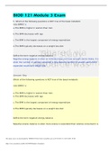
1-1. Equilibrium of forces at node A is shown graphically in Fig. F = 10
1-1. Because 5 3 ≈ 8.7 , No. 5 is correct.
P AC = 5
Fig. 1-1
1-2. Noting that (stress) = (axial force)/(cross-sectional area), the stresses of members AB and AC
are
PAB 5 3 PAC 5
σ AB = = (kN/mm 2 ) and σ AC = = (kN/mm 2 )
A 100 A 100
Because (strain) = (stress)/(Young’s modulus), strains in members AB and AC are
σ AB 5 3 σ AC 5
ε AB = = (No unit) and ε AC = = (No unit)
E 100 × 200 E 100 × 200
Recalling (deformation) = (strain)x(length), we have
5 3 5 3
eAB = ε AB × LAB = × 10, 000 = ≈ 4.3 ( mm )
100 × 200 2
5 5 3
eAC = ε AC × LAC = × 10, 000 3 = ≈ 4.3 ( mm )
100 × 200 2
No. 3 is correct.
1-3. Because the strength of the material is 200 N/mm2 and its cross-sectional area is 100 mm2, the
maximum possible axial force is 200 x 100 = 20 kN. On the other hand, the axial forces in members
AB and AC caused by an external force F are as follows (see Fig. 1-1).
394
, 2007/10/25
3 1
PAB = F PAC = F
2 2
Noting that PAB is larger than PAC, we can assume that the truss fails if PAB = 20 kN.
3 2
PAB = F = 20 leads to F = × 20 ≈ 23.1 (kN )
2 3
No. 4 is correct.
1-4. Equilibrium of the moments around support A leads to a reaction at support E expressed as
5
RE = × 20 = 5 ( N) .
20
Equilibrium of vertical forces leads to
RA = 20 − RE = 15 ( N) .
Equilibrium at joint A shown in Fig. 1-2a yields PAC = 15 kN, while equilibrium at joint E shown in
Fig. 1-2b yields PCE = 5 kN.
No. 1 is correct.
PAB PDE
PAB PDE
A PAC 15 kN 5 kN
E
PAC PCE PCE
15 kN 5 kN
(a) Equilibrium at node A (b) Equilibrium at node E
Fig. 1-2
1-5. The elongations of members AC and CE are calculated as below.
395