genius PHYSICS
Magnetic Effect of Current 1
1
Oersted found that a magnetic field is established around a current
Magnetic lines
carrying conductor. i of forces
Magnetic field exists as long as there is current in the wire.
The direction of magnetic field was found to be changed when direction of
current was reversed.
Note : A moving charge produces magnetic as well as electric field,
unlike a stationary charge which only produces electric field.
Biot Savart's Law.
Biot-Savart’s law is used to determine the magnetic field at any point due to a current carrying
conductors.
This law is although for infinitesimally small conductors yet it can be used for long conductors. In order to
understand the Biot-Savart’s law, we need to understand the term current-element.
Current element
It is the product of current and length of infinitesimal segment of current carrying wire.
B
A
The current element is taken as a vector quantity. Its direction is same as the direction of current.
i
dl
Current element AB = i dl
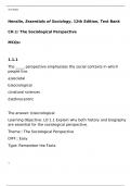
In the figure shown below, there is a segment of current carrying wire and P is a point where magnetic
field is to be calculated. i d l is a current element and r is the distance of the point ‘P’ with respect to the current
element i d l . According to Biot-Savart Law, magnetic field at point ‘P’ due to the current element i d l is given
i dlsin θ 0 i dl sin
by the expression, dB k
r 2
also B dB
4 r 2
.
P
idl sin
In C.G.S. : k = 1 dB Gauss dl r
r2
i
0 idl sin
In S.I. : k dB 0 Tesla
4 4 r2
Wb Henry
where 0 = Absolute permeability of air or vacuum 4 10 7 . It's other units are
Amp metre metre
N Tesla metre
or 2
or
Amp Ampere
,2 Magnetic Effect of Current
genius PHYSICS
(1) Different forms of Biot-Savarts law
Vector form Biot-Savarts law in terms of Biot-savarts law in terms of
current density charge and it's velocity
Vectorially, In terms of current density In terms of charge and it’s velocity,
i(d l rˆ ) i(d l r ) J r (v r )
dB 0
0
dB 0 dV dB 0 q 3
4 r2 4 r3 4 r 3 4 r
Direction of d B is perpendicular to i idl idl q dl
where j = current id l dl q qv
both d l and r̂ . This is given by A Adl dV dt dt
right hand screw rule. density at any point of the element,
dV = volume of element
(2) Similarities and differences between Biot-Savart law and Coulomb’s Law
(i) The current element produces a magnetic field, whereas a point charge produces an electric field.
(ii) The magnitude of magnetic field varies as the inverse square of the distance from the current element,
as does the electric field due to a point charge.
0 id l rˆ 1 q1 q 2
dB Biot-Savart Law F rˆ Coulomb’s Law
4 r 2 4 0 r2
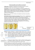
(iii) The electric field created by a point charge is radial, but the magnetic field created by a current
element is perpendicular to both the length element d l and the unit vector r̂ .
dl E
i
r̂ B
+q r̂
Direction of Magnetic Field.
The direction of magnetic field is determined with the help of the following simple laws :
(1) Maxwell’s cork screw rule
According to this rule, if we imagine a right handed screw placed along the current
carrying linear conductor, be rotated such that the screw moves in the direction of flow of
current, then the direction of rotation of the thumb gives the direction of magnetic lines of
force.
(2) Right hand thumb rule
According to this rule if a current carrying conductor is held in the right hand such
that the thumb of the hand represents the direction of current flow, then the direction of
folding fingers will represent the direction of magnetic lines of force. B
B
(3) Right hand thumb rule of circular currents
According to this rule if the direction of current in circular i
, genius PHYSICS
Magnetic Effect of Current 3
3
conducting coil is in the direction of folding fingers of right hand, then the direction of magnetic field will be in
the direction of stretched thumb.
(4) Right hand palm rule
If we stretch our right hand such that fingers point towards the point. At
which magnetic field is required while thumb is in the direction of current then
normal to the palm will show the direction of magnetic field.
B
Note : If magnetic field is directed perpendicular and into the plane of the paper it is represented by
(cross) while if magnetic field is directed perpendicular and out of the plane of the paper it is
represented by (dot)
i i
i i CW ACW
B B B B
Out In In Out
In Out
In : Magnetic field is away from the observer or perpendicular inwards.
Out : Magnetic field is towards the observer or perpendicular outwards.
Application of Biot-Savarts Law.
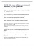
(1) Magnetic field due to a circular current
If a coil of radius r, carrying current i then magnetic field on it's axis at a distance x from its centre given
by
μ0 2 πNir 2
B axis . 2 ; where N = number of turns in coil.
4 π ( x r 2 ) 3/2 r
P
B
Different cases O x
i
Case 1 : Magnetic field at the centre of the coil
0 2Ni Ni
(i) At centre x = 0 Bcentre . = 0 B max
4 r 2r
2i 0 i 0 2i
(ii) For single turn coil N = 1 Bcentre 0 . (iii) In C.G.S. 1 B centre
4 r 2r 4 r
Note : Bcentre N (i, r constant), Bcentre i (N, r constant), B centre
1
(N, i constant)
r
Case 2 : Ratio of Bcentre and Baxis
3/2
B x2
The ratio of magnetic field at the centre of circular coil and on it's axis is given by centre 1 2
B axis r
3/2
a 5 5 a 3
(i) If x a, Bc 2 2 Ba x , Bc Ba x , Bc Ba
2 8 2 2
Bc B
(ii) If B a then x r (n 1) and if B a c then x r (n 1)
n n
Case 3 : Magnetic field at very large/very small distance from the centre
, 4 Magnetic Effect of Current
genius PHYSICS
0 2 Nir 2 0 2 NiA
(i) If x >> r (very large distance) B axis
. . where A = r2 = Area of each turn of the coil.
4 x3 4 x 3
(ii) If x << r (very small distance) Baxis Bcentre , but by using binomial theorem and neglecting higher
x2 3 x2
power of ; B B 1
r2
axis centre 2
2 r
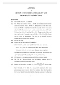
Case 4 : B-x curve
The variation of magnetic field due to a circular coil as the distance x varies as shown in the figure.
B varies non-linearly with distance x as shown in figure and is maximum when x 2 min 0 , i.e., the
point is at the centre of the coil and it is zero at x = .
Point of inflection (A and A) : Also known as points of curvature change or pints of zero curvature.
dB
(i) At these points B varies linearly with x constant
dx
d 2B
0. A A
dx 2 B0
r
(ii) They locates at x from the centre of the coil.
2 x = – r/2 x = 0 x = r/2
(iii) Separation between point of inflextion is equal to radius of coil (r)
(iv) Application of points of inflextion is "Hamholtz coils" arrangement.
Note : The magnetic field at x
r
is B
4 0 Ni
2 5 5r
(2) Helmholtz coils
(i) This is the set-up of two coaxial coils of same radius such that distance between their centres is equal to their
radius.
(ii) These coils are used to obtain uniform magnetic field of short range which is obtained between the
coils.
8 0 Ni 0 Ni 0 Ni
(iii) At axial mid point O, magnetic field is given by B 0 .716 1 .432 B , where B
5 5R R 2R
(iv) Current direction is same in both coils otherwise this arrangement is not called Helmholtz's coil
arrangement.
(v) Number of points of inflextion Three (A, A, A)
Resultant field (Uniform)
a a
O A A A
O1 O2
O1 O O2 x
+ +
a a
– – x x
2 2
Note : The device whose working principle based on this arrangement and in which uniform
magnetic field is used called as "Halmholtz galvanometer".
(3) Magnetic field due to current carrying circular arc : Magnetic field at centre O
Magnetic Effect of Current 1
1
Oersted found that a magnetic field is established around a current
Magnetic lines
carrying conductor. i of forces
Magnetic field exists as long as there is current in the wire.
The direction of magnetic field was found to be changed when direction of
current was reversed.
Note : A moving charge produces magnetic as well as electric field,
unlike a stationary charge which only produces electric field.
Biot Savart's Law.
Biot-Savart’s law is used to determine the magnetic field at any point due to a current carrying
conductors.
This law is although for infinitesimally small conductors yet it can be used for long conductors. In order to
understand the Biot-Savart’s law, we need to understand the term current-element.
Current element
It is the product of current and length of infinitesimal segment of current carrying wire.
B
A
The current element is taken as a vector quantity. Its direction is same as the direction of current.
i
dl
Current element AB = i dl
In the figure shown below, there is a segment of current carrying wire and P is a point where magnetic
field is to be calculated. i d l is a current element and r is the distance of the point ‘P’ with respect to the current
element i d l . According to Biot-Savart Law, magnetic field at point ‘P’ due to the current element i d l is given
i dlsin θ 0 i dl sin
by the expression, dB k
r 2
also B dB
4 r 2
.
P
idl sin
In C.G.S. : k = 1 dB Gauss dl r
r2
i
0 idl sin
In S.I. : k dB 0 Tesla
4 4 r2
Wb Henry
where 0 = Absolute permeability of air or vacuum 4 10 7 . It's other units are
Amp metre metre
N Tesla metre
or 2
or
Amp Ampere
,2 Magnetic Effect of Current
genius PHYSICS
(1) Different forms of Biot-Savarts law
Vector form Biot-Savarts law in terms of Biot-savarts law in terms of
current density charge and it's velocity
Vectorially, In terms of current density In terms of charge and it’s velocity,
i(d l rˆ ) i(d l r ) J r (v r )
dB 0
0
dB 0 dV dB 0 q 3
4 r2 4 r3 4 r 3 4 r
Direction of d B is perpendicular to i idl idl q dl
where j = current id l dl q qv
both d l and r̂ . This is given by A Adl dV dt dt
right hand screw rule. density at any point of the element,
dV = volume of element
(2) Similarities and differences between Biot-Savart law and Coulomb’s Law
(i) The current element produces a magnetic field, whereas a point charge produces an electric field.
(ii) The magnitude of magnetic field varies as the inverse square of the distance from the current element,
as does the electric field due to a point charge.
0 id l rˆ 1 q1 q 2
dB Biot-Savart Law F rˆ Coulomb’s Law
4 r 2 4 0 r2
(iii) The electric field created by a point charge is radial, but the magnetic field created by a current
element is perpendicular to both the length element d l and the unit vector r̂ .
dl E
i
r̂ B
+q r̂
Direction of Magnetic Field.
The direction of magnetic field is determined with the help of the following simple laws :
(1) Maxwell’s cork screw rule
According to this rule, if we imagine a right handed screw placed along the current
carrying linear conductor, be rotated such that the screw moves in the direction of flow of
current, then the direction of rotation of the thumb gives the direction of magnetic lines of
force.
(2) Right hand thumb rule
According to this rule if a current carrying conductor is held in the right hand such
that the thumb of the hand represents the direction of current flow, then the direction of
folding fingers will represent the direction of magnetic lines of force. B
B
(3) Right hand thumb rule of circular currents
According to this rule if the direction of current in circular i
, genius PHYSICS
Magnetic Effect of Current 3
3
conducting coil is in the direction of folding fingers of right hand, then the direction of magnetic field will be in
the direction of stretched thumb.
(4) Right hand palm rule
If we stretch our right hand such that fingers point towards the point. At
which magnetic field is required while thumb is in the direction of current then
normal to the palm will show the direction of magnetic field.
B
Note : If magnetic field is directed perpendicular and into the plane of the paper it is represented by
(cross) while if magnetic field is directed perpendicular and out of the plane of the paper it is
represented by (dot)
i i
i i CW ACW
B B B B
Out In In Out
In Out
In : Magnetic field is away from the observer or perpendicular inwards.
Out : Magnetic field is towards the observer or perpendicular outwards.
Application of Biot-Savarts Law.
(1) Magnetic field due to a circular current
If a coil of radius r, carrying current i then magnetic field on it's axis at a distance x from its centre given
by
μ0 2 πNir 2
B axis . 2 ; where N = number of turns in coil.
4 π ( x r 2 ) 3/2 r
P
B
Different cases O x
i
Case 1 : Magnetic field at the centre of the coil
0 2Ni Ni
(i) At centre x = 0 Bcentre . = 0 B max
4 r 2r
2i 0 i 0 2i
(ii) For single turn coil N = 1 Bcentre 0 . (iii) In C.G.S. 1 B centre
4 r 2r 4 r
Note : Bcentre N (i, r constant), Bcentre i (N, r constant), B centre
1
(N, i constant)
r
Case 2 : Ratio of Bcentre and Baxis
3/2
B x2
The ratio of magnetic field at the centre of circular coil and on it's axis is given by centre 1 2
B axis r
3/2
a 5 5 a 3
(i) If x a, Bc 2 2 Ba x , Bc Ba x , Bc Ba
2 8 2 2
Bc B
(ii) If B a then x r (n 1) and if B a c then x r (n 1)
n n
Case 3 : Magnetic field at very large/very small distance from the centre
, 4 Magnetic Effect of Current
genius PHYSICS
0 2 Nir 2 0 2 NiA
(i) If x >> r (very large distance) B axis
. . where A = r2 = Area of each turn of the coil.
4 x3 4 x 3
(ii) If x << r (very small distance) Baxis Bcentre , but by using binomial theorem and neglecting higher
x2 3 x2
power of ; B B 1
r2
axis centre 2
2 r
Case 4 : B-x curve
The variation of magnetic field due to a circular coil as the distance x varies as shown in the figure.
B varies non-linearly with distance x as shown in figure and is maximum when x 2 min 0 , i.e., the
point is at the centre of the coil and it is zero at x = .
Point of inflection (A and A) : Also known as points of curvature change or pints of zero curvature.
dB
(i) At these points B varies linearly with x constant
dx
d 2B
0. A A
dx 2 B0
r
(ii) They locates at x from the centre of the coil.
2 x = – r/2 x = 0 x = r/2
(iii) Separation between point of inflextion is equal to radius of coil (r)
(iv) Application of points of inflextion is "Hamholtz coils" arrangement.
Note : The magnetic field at x
r
is B
4 0 Ni
2 5 5r
(2) Helmholtz coils
(i) This is the set-up of two coaxial coils of same radius such that distance between their centres is equal to their
radius.
(ii) These coils are used to obtain uniform magnetic field of short range which is obtained between the
coils.
8 0 Ni 0 Ni 0 Ni
(iii) At axial mid point O, magnetic field is given by B 0 .716 1 .432 B , where B
5 5R R 2R
(iv) Current direction is same in both coils otherwise this arrangement is not called Helmholtz's coil
arrangement.
(v) Number of points of inflextion Three (A, A, A)
Resultant field (Uniform)
a a
O A A A
O1 O2
O1 O O2 x
+ +
a a
– – x x
2 2
Note : The device whose working principle based on this arrangement and in which uniform
magnetic field is used called as "Halmholtz galvanometer".
(3) Magnetic field due to current carrying circular arc : Magnetic field at centre O