Principles of DC Machines
Generator Action
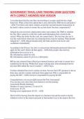
• Consider a conductor of length L that is at a right angle to a magnetic field of flux
density B
o the conductor can move along a set of parallel rails
o an external voltmeter records the voltage between a and b
o if the conductor moves with relative speed v the voltage recorded by the
voltmeter is given by:
𝑒 = 𝐵𝐿𝑣
o the voltage polarity is indicated in the figure
o NOTE: by reversing the direction of the magnetic field B or the direction of
motion of the conductor -> polarity will reverse
o Terminal polarity is determined using Fleming’s Right Hand Rule (a.k.a
generator rule)
• If the conductor is not perpendicular to the magnetic field
o Generated emf will be smaller
o If 𝜃 = 90°, there will be no generated voltage
o The generated voltage is now given by:
𝑒 = 𝐵𝐿𝑣𝑐𝑜𝑠𝜃
, Elementary Generator
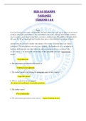
• Elementary generator consists of a wire loop that can rotate in a stationary magnetic
field
o This will produce an induced EMF in the loop
• Sliding contacts (a.k.a brushes) connect the loop to an external circuit load in order
to use the induced EMF – usually made of carbon
• The North and South poles provide a magnetic field – pole pieces are shaped as
shown to concentrate the magnetic field closely to the loop
• The loop of wire is called an armature
o The ends of the armature are connected to rings called slip rings which ride
against the brushes
• The voltage produced by the elementary generator is of the form of sinewave
o The initial/ starting point A is considered the zero degree position – armature
loop is perpendicular to the magnetic field which means the conductors are
moving parallel to the magnetic field (no emf is induced). This is called the
NEUTRAL PLANE
o Armature rotates from position A (0°) to position B (90°)
o At 90° the conductors cut through the maximum flux lines at the maximum
angle – thus maximum EMF value
o Note one conductor cuts DOWN through the field while the other cuts UP ->
the resultant voltage is the sum of the two induced voltages
Generator Action
• Consider a conductor of length L that is at a right angle to a magnetic field of flux
density B
o the conductor can move along a set of parallel rails
o an external voltmeter records the voltage between a and b
o if the conductor moves with relative speed v the voltage recorded by the
voltmeter is given by:
𝑒 = 𝐵𝐿𝑣
o the voltage polarity is indicated in the figure
o NOTE: by reversing the direction of the magnetic field B or the direction of
motion of the conductor -> polarity will reverse
o Terminal polarity is determined using Fleming’s Right Hand Rule (a.k.a
generator rule)
• If the conductor is not perpendicular to the magnetic field
o Generated emf will be smaller
o If 𝜃 = 90°, there will be no generated voltage
o The generated voltage is now given by:
𝑒 = 𝐵𝐿𝑣𝑐𝑜𝑠𝜃
, Elementary Generator
• Elementary generator consists of a wire loop that can rotate in a stationary magnetic
field
o This will produce an induced EMF in the loop
• Sliding contacts (a.k.a brushes) connect the loop to an external circuit load in order
to use the induced EMF – usually made of carbon
• The North and South poles provide a magnetic field – pole pieces are shaped as
shown to concentrate the magnetic field closely to the loop
• The loop of wire is called an armature
o The ends of the armature are connected to rings called slip rings which ride
against the brushes
• The voltage produced by the elementary generator is of the form of sinewave
o The initial/ starting point A is considered the zero degree position – armature
loop is perpendicular to the magnetic field which means the conductors are
moving parallel to the magnetic field (no emf is induced). This is called the
NEUTRAL PLANE
o Armature rotates from position A (0°) to position B (90°)
o At 90° the conductors cut through the maximum flux lines at the maximum
angle – thus maximum EMF value
o Note one conductor cuts DOWN through the field while the other cuts UP ->
the resultant voltage is the sum of the two induced voltages