ES1960
THE UNIVERSITY OF WARWICK
First Year Examinations: January 2018
STATICS AND STRUCTURES
This examination is split into four questions, each worth 25 marks.
Candidates should answer ALL FOUR QUESTIONS.
Numerical solutions lacking units are considered incomplete.
Time allowed: 3 hours.
Only calculators that confirm to the list of models approved by the School of Engineering may be
used in this examination. The Engineering Data Book and standard graph paper will be provided.
Read carefully the instructions on the answer booklets and ensure the details required are written on
every booklet submitted.
,ES1960
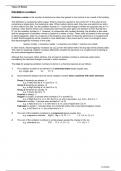
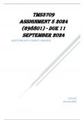
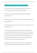
Q1. The beam AB shown in Figure 1 has a moment applied at point C, a point load with an
inclination of 60º at point D and a distributed load acting from point E to point B. For the
beam AB:
(i) Determine the external reaction forces at A and B. (6 marks)
(ii) Derive the equations for calculating the internal axial force, shear force and bending
moment at any point along the beam. (10 marks)
(iii) Draw the diagrams of the internal axial force, shear force and bending moment.
(9 marks)
Figure 1
[Total 25 marks]
Continued
2
, ES1960
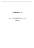
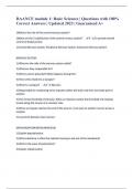
Q2. Figure 2 shows a plane pin-jointed truss supported by a pin-joint at A and a roller joint at
B. Lengths of the structure are as given in Figure 2, and all the angles are either 45º or
90º. The frame is subjected to two vertical forces of 20 kN and 50 kN at E and G,
respectively. All members have the same cross section area A of 250 mm2 and modulus
of elasticity E of 50 GPa.
(i) Determine the reaction forces at A and B. (5 marks)
(ii) Find the forces in members CD, DE, CG, GF and GE, stating explicitly whether
they are in tension or compression. (12 marks)
(iii) Calculate the horizontal displacement of node B. (Hint: The horizontal
displacement of point B is calculated using the formula
= ∑n.bars
=1 , where Li represents the length of each bar, E is the
modulus of elasticity, A is the cross section area of each bar, and represent
the axial forces acting on the i-th element for the initial system and the system with
a virtual load applied to the node of interest, respectively). (8 marks)
Figure 2
[Total 25 marks]
Continued
3
THE UNIVERSITY OF WARWICK
First Year Examinations: January 2018
STATICS AND STRUCTURES
This examination is split into four questions, each worth 25 marks.
Candidates should answer ALL FOUR QUESTIONS.
Numerical solutions lacking units are considered incomplete.
Time allowed: 3 hours.
Only calculators that confirm to the list of models approved by the School of Engineering may be
used in this examination. The Engineering Data Book and standard graph paper will be provided.
Read carefully the instructions on the answer booklets and ensure the details required are written on
every booklet submitted.
,ES1960
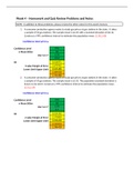
Q1. The beam AB shown in Figure 1 has a moment applied at point C, a point load with an
inclination of 60º at point D and a distributed load acting from point E to point B. For the
beam AB:
(i) Determine the external reaction forces at A and B. (6 marks)
(ii) Derive the equations for calculating the internal axial force, shear force and bending
moment at any point along the beam. (10 marks)
(iii) Draw the diagrams of the internal axial force, shear force and bending moment.
(9 marks)
Figure 1
[Total 25 marks]
Continued
2
, ES1960
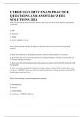
Q2. Figure 2 shows a plane pin-jointed truss supported by a pin-joint at A and a roller joint at
B. Lengths of the structure are as given in Figure 2, and all the angles are either 45º or
90º. The frame is subjected to two vertical forces of 20 kN and 50 kN at E and G,
respectively. All members have the same cross section area A of 250 mm2 and modulus
of elasticity E of 50 GPa.
(i) Determine the reaction forces at A and B. (5 marks)
(ii) Find the forces in members CD, DE, CG, GF and GE, stating explicitly whether
they are in tension or compression. (12 marks)
(iii) Calculate the horizontal displacement of node B. (Hint: The horizontal
displacement of point B is calculated using the formula
= ∑n.bars
=1 , where Li represents the length of each bar, E is the
modulus of elasticity, A is the cross section area of each bar, and represent
the axial forces acting on the i-th element for the initial system and the system with
a virtual load applied to the node of interest, respectively). (8 marks)
Figure 2
[Total 25 marks]
Continued
3