Computer Organization 2018
Midterm Endterm
Chapter 1 Chapter 1
Chapter 2 Chapter 3 (all but “An example of…”)
Chapter 9 (all but 9.2, 9.5 and 9.6) Chapter 5
Appendix A (all but A.11 and A.12) Chapter 6 (all but 6.10)
Chapter 7 (7.1 through 7.3)
Chapter 8 (8.1, 8.2, 8.4 through 8.7)
Chapter 12
,Appendix A
A.1 Basic Logic Functions
In this paragraph the AND, OR, NOT and XOR function are introduced. Furthermore, electronic
logic gates and their symbols are shown.
A.2 Syntheses of Logic Functions
Hierarchy of operators in an expression in absence of parentheses: NOT – AND – OR – XOR.
Shown here is how we can extract an expression in the form of a sum-of-products from a given
truth table.
A.3 Minimization of Logic Expressions
Definition of two equivalent logic gate networks: if the expressions have the same truth tables.
Therefore, we can use the truth-table technique for proving equivalence of expressions.
The objective in minimal logic minimization is to simplify an expression to an equivalent minimal
sum of products expression. The usual cost measure: total number of gates + gate inputs.
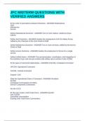
To simplify a given expression we can use:
• The rules of binary logic (see table below);
• Karnaugh Maps;
Name Algebraic identity Some more rules
Commutative 𝑤+𝑦 =𝑦+𝑤 𝑤𝑦 = 𝑦𝑤 𝑤 + 𝑤𝑦 = 𝑤
Associative (𝑤 + 𝑦) + 𝑧 = 𝑤 + (𝑦 + 𝑧) (𝑤𝑦)𝑧 = 𝑤(𝑦𝑧)
Distributive 𝑤 + 𝑦𝑧 = (𝑤 + 𝑦)(𝑤 + 𝑧) 𝑤(𝑦 + 𝑧) = 𝑤𝑦 + 𝑤𝑧
Idempotent 𝑤+𝑤 =𝑤 𝑤𝑤 = 𝑤
Involution 𝑤
̿ =𝑤
Complement 𝑤
̅ +𝑤 =1 𝑤
̅𝑤 = 0
De Morgan ̅̅̅̅̅̅̅̅
𝑤+𝑦 = 𝑤 ̅𝑦̅ ̅̅̅̅ = 𝑤
𝑤𝑦 ̅ + 𝑦̅
1+𝑤 =1 0∗𝑤 =0
0+𝑤 =𝑤 1∗𝑤 =𝑤
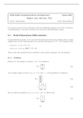
Simplifying an expression using a Karnaugh Map:
1. Create a truth table;
2. Use the different representation of a truth table;
3. Group adjacent squares containing 1s, the number of squares in any valid group must be
equal to 2𝑘 , where 𝑘 is an integer.
• Choose the smallest set of groups, pick large groups wherever possible.
• It is often the case that a given function has more than one minimal expression.
In many situations, some valuations of the inputs to a digital circuit never occur. We do not care
what the function values for the unused input valuations are, they are called don’t-cares. Don’t-
care condition can be assigned to be either 0 or 1, the best way to assign them is in a manner that
will lead to a minimal logic gate implementation (interpret as 1s when they can enlarge a group).
The SOP (sum-of-products form) can be inferred from the Karnaugh Map of 𝑓.
The POS (products-of-sum form) can be made using these steps:
1. Create the SOP of 𝑓,̅ two ways to find this expression:
a. Create the Karnaugh Map of 𝑓 ̅ (easily inferred of the Karnaugh Map of 𝑓);
b. Complement the SOP expression of 𝑓 and simplify to a SOP expression;
2. Complement the SOP expression of 𝑓 ̅ to find an expression for 𝑓 (because 𝑓 ̿ = 𝑓);
𝑓 (SOP) → 𝑓 ̅ → 𝑓 ̿ → 𝑓 (POS). For some functions, the POS implementation is less expensive than
the SOP implementation, and vice versa.
, A.4 Synthesis with NAND and NOR gates
In this paragraph, two other basic logic gates called NAND and NOR are introduced.
There is a direct way to translate a logic network expressed in sum-of-products into an equivalent
network composed only of NAND gates or NOR gates. Any logic network can be synthesized in a
sum-of-products form. Therefore, any logic network can be synthesized in a NAND-NAND form or
a NOR-NOR form.
Difficulty in design process: the associative rule is not valid for NAND and NOR operators.
Therefore, a three-input NAND or NOR function cannot be implemented by a cascade of 2 two-
input gates.
A.5 Practical Implementation of Logic Gates
Threshold: voltages above a given threshold are taken to represent one logic value and voltages
below that threshold representing the other.
Forbidden range: logic state corresponding to a voltage level near the threshold cannot be reliably
determined, because the voltage at any point in an electronic circuit undergoes small random
variations.
Transistor: functions as an open switch when the input voltage applied to the gate of the transistor
is 0 and the transistor acts as a closed switch when the input voltage equals the supply voltage.
n-channel transistor of NMOS type: gate input raised to positive power supply → closed switch.
p-channel transistor of PMOS type: gate input raised to positive power supple → open switch.
• Graphical symbol of PMOS type has bubble on the gate input to indicate that its behavior is
complementary to that of an NMOS transistor.
• Source of NMOS is connected to the ground, source of PMOS is connected to 𝑉𝑠𝑢𝑝𝑝𝑙𝑦 .
CMOS technology: using both NMOS and PMOS transistors to implement circuits that do not
dissipate power when in a steady state. They only dissipate power when switching from one logic
state to another.
• NMOS transistors are used to implement the pull-down network, such that a closed path is
established between the output point 𝑓 and the ground when 𝐹(𝑥1 , … , 𝑥𝑛 ) is equal to 0.
• PMOS transistors are used to implement the pull-up network, such that a closed path is
established between the output point 𝑓 and 𝑉𝑠𝑢𝑝𝑝𝑙𝑦 when 𝐹(𝑥1 , … , 𝑥𝑛 ) is equal to 1.
• In a steady state there exists a closed path only between the output 𝑓 and either 𝑉𝑠𝑢𝑝𝑝𝑙𝑦 or
ground, but not both.
• Circuits that use lower power supply voltages dissipate much less power.
The maximum speed at which a logical circuit can be operated decreases as the propagation
delay (definition see p.490) through different paths within that circuit increases. The delay along
any path in a logic circuit is the sum of individual gate delays along this path.
Fan-in: the number of inputs to a logic gate.
Fan-out: the number of gate inputs that the output of a logic gate drives (number of gates
connected to the output).
Tri-state-buffer has three states.
• Two of the states produce normal 0 and 1 signals;
• The third state places the output terminal of the buffer into a high-impedance state in which
the output is electrically disconnected from the input it is supposed to drive.
Midterm Endterm
Chapter 1 Chapter 1
Chapter 2 Chapter 3 (all but “An example of…”)
Chapter 9 (all but 9.2, 9.5 and 9.6) Chapter 5
Appendix A (all but A.11 and A.12) Chapter 6 (all but 6.10)
Chapter 7 (7.1 through 7.3)
Chapter 8 (8.1, 8.2, 8.4 through 8.7)
Chapter 12
,Appendix A
A.1 Basic Logic Functions
In this paragraph the AND, OR, NOT and XOR function are introduced. Furthermore, electronic
logic gates and their symbols are shown.
A.2 Syntheses of Logic Functions
Hierarchy of operators in an expression in absence of parentheses: NOT – AND – OR – XOR.
Shown here is how we can extract an expression in the form of a sum-of-products from a given
truth table.
A.3 Minimization of Logic Expressions
Definition of two equivalent logic gate networks: if the expressions have the same truth tables.
Therefore, we can use the truth-table technique for proving equivalence of expressions.
The objective in minimal logic minimization is to simplify an expression to an equivalent minimal
sum of products expression. The usual cost measure: total number of gates + gate inputs.
To simplify a given expression we can use:
• The rules of binary logic (see table below);
• Karnaugh Maps;
Name Algebraic identity Some more rules
Commutative 𝑤+𝑦 =𝑦+𝑤 𝑤𝑦 = 𝑦𝑤 𝑤 + 𝑤𝑦 = 𝑤
Associative (𝑤 + 𝑦) + 𝑧 = 𝑤 + (𝑦 + 𝑧) (𝑤𝑦)𝑧 = 𝑤(𝑦𝑧)
Distributive 𝑤 + 𝑦𝑧 = (𝑤 + 𝑦)(𝑤 + 𝑧) 𝑤(𝑦 + 𝑧) = 𝑤𝑦 + 𝑤𝑧
Idempotent 𝑤+𝑤 =𝑤 𝑤𝑤 = 𝑤
Involution 𝑤
̿ =𝑤
Complement 𝑤
̅ +𝑤 =1 𝑤
̅𝑤 = 0
De Morgan ̅̅̅̅̅̅̅̅
𝑤+𝑦 = 𝑤 ̅𝑦̅ ̅̅̅̅ = 𝑤
𝑤𝑦 ̅ + 𝑦̅
1+𝑤 =1 0∗𝑤 =0
0+𝑤 =𝑤 1∗𝑤 =𝑤
Simplifying an expression using a Karnaugh Map:
1. Create a truth table;
2. Use the different representation of a truth table;
3. Group adjacent squares containing 1s, the number of squares in any valid group must be
equal to 2𝑘 , where 𝑘 is an integer.
• Choose the smallest set of groups, pick large groups wherever possible.
• It is often the case that a given function has more than one minimal expression.
In many situations, some valuations of the inputs to a digital circuit never occur. We do not care
what the function values for the unused input valuations are, they are called don’t-cares. Don’t-
care condition can be assigned to be either 0 or 1, the best way to assign them is in a manner that
will lead to a minimal logic gate implementation (interpret as 1s when they can enlarge a group).
The SOP (sum-of-products form) can be inferred from the Karnaugh Map of 𝑓.
The POS (products-of-sum form) can be made using these steps:
1. Create the SOP of 𝑓,̅ two ways to find this expression:
a. Create the Karnaugh Map of 𝑓 ̅ (easily inferred of the Karnaugh Map of 𝑓);
b. Complement the SOP expression of 𝑓 and simplify to a SOP expression;
2. Complement the SOP expression of 𝑓 ̅ to find an expression for 𝑓 (because 𝑓 ̿ = 𝑓);
𝑓 (SOP) → 𝑓 ̅ → 𝑓 ̿ → 𝑓 (POS). For some functions, the POS implementation is less expensive than
the SOP implementation, and vice versa.
, A.4 Synthesis with NAND and NOR gates
In this paragraph, two other basic logic gates called NAND and NOR are introduced.
There is a direct way to translate a logic network expressed in sum-of-products into an equivalent
network composed only of NAND gates or NOR gates. Any logic network can be synthesized in a
sum-of-products form. Therefore, any logic network can be synthesized in a NAND-NAND form or
a NOR-NOR form.
Difficulty in design process: the associative rule is not valid for NAND and NOR operators.
Therefore, a three-input NAND or NOR function cannot be implemented by a cascade of 2 two-
input gates.
A.5 Practical Implementation of Logic Gates
Threshold: voltages above a given threshold are taken to represent one logic value and voltages
below that threshold representing the other.
Forbidden range: logic state corresponding to a voltage level near the threshold cannot be reliably
determined, because the voltage at any point in an electronic circuit undergoes small random
variations.
Transistor: functions as an open switch when the input voltage applied to the gate of the transistor
is 0 and the transistor acts as a closed switch when the input voltage equals the supply voltage.
n-channel transistor of NMOS type: gate input raised to positive power supply → closed switch.
p-channel transistor of PMOS type: gate input raised to positive power supple → open switch.
• Graphical symbol of PMOS type has bubble on the gate input to indicate that its behavior is
complementary to that of an NMOS transistor.
• Source of NMOS is connected to the ground, source of PMOS is connected to 𝑉𝑠𝑢𝑝𝑝𝑙𝑦 .
CMOS technology: using both NMOS and PMOS transistors to implement circuits that do not
dissipate power when in a steady state. They only dissipate power when switching from one logic
state to another.
• NMOS transistors are used to implement the pull-down network, such that a closed path is
established between the output point 𝑓 and the ground when 𝐹(𝑥1 , … , 𝑥𝑛 ) is equal to 0.
• PMOS transistors are used to implement the pull-up network, such that a closed path is
established between the output point 𝑓 and 𝑉𝑠𝑢𝑝𝑝𝑙𝑦 when 𝐹(𝑥1 , … , 𝑥𝑛 ) is equal to 1.
• In a steady state there exists a closed path only between the output 𝑓 and either 𝑉𝑠𝑢𝑝𝑝𝑙𝑦 or
ground, but not both.
• Circuits that use lower power supply voltages dissipate much less power.
The maximum speed at which a logical circuit can be operated decreases as the propagation
delay (definition see p.490) through different paths within that circuit increases. The delay along
any path in a logic circuit is the sum of individual gate delays along this path.
Fan-in: the number of inputs to a logic gate.
Fan-out: the number of gate inputs that the output of a logic gate drives (number of gates
connected to the output).
Tri-state-buffer has three states.
• Two of the states produce normal 0 and 1 signals;
• The third state places the output terminal of the buffer into a high-impedance state in which
the output is electrically disconnected from the input it is supposed to drive.