P2 - explain which features of CAD drawings need to comply with national and international
standards.
Features of CAD drawings that need to comply with national and international standards include:
CAD layers
Lines – types and sizes
Annotation—text, dimensions and tables
Scales
File handling – file naming, data transfer
Geometric dimensioning and tolerancing
Geometric quality
Drawing sheets – sizes and layouts
Projections – first and third angles
Lettering
Numbering
Symbols
Standards used for CAD engineering drawings:
BS 8888
BS 8888 is a part of the UK’s national framework making it arguably the most commonly used British standard. It is
used for engineering drawings and geometrical tolerancing and includes details like the types and sized of nuts and
bolts used in engineering drawings. Furthermore, it also covers the requirements for the technical products specs
of products and component parts. It was created by combining all international standards needed to devise
product specifications, also known as product specs. The aim of products specs is to provide the product design
team with enough information to allow them to successfully create new product features that enhance the design
and match the expectations of the company and the customer.
The aim of the standard is to help the UK engineering industry move towards the ISO (International Organization
for Standarization) system of geometrical product specification.
BS 8888 covers all symbols and information necessary to include in engineering drawings regardless of whether
they are created manually (drawn by hand) or with CAD or 3D modelling as well as whether they are 2 or 3
dimensional. Its purpose is to explain the way in which drawings outline and present certain specifications.
BS 8888 standardizes important features of engineering drawing such as:
Drawing sheets
According to BS 8888 drawing sheets must be produced with accordance to BS EN ISO 5457 and BS EN ISO 7200.
ISO 7200 is a standard that sets out data fields (spaces used for storing data) used in headers and title blocks. It
standardizes features like names, contents and maximum number of characters used for each field.
ISO 7200 discusses possible issues such as data transfer. For example, how to move certain data in an ordered
form or sharing only certain segments of a document.
, The standard prioritized consistency and structure by guiding the user through how one should sort items by
characteristics into classes and subclasses.
ISO 5457 treats about the sizes and layouts of drawing sheets, including borders, trimming marks and frames. It
also provides a guide to the size system of drawing sheets as well as title blocks. Moreover, it also provides
examples of drawing sheets of varying sizes (from A0 to A4).
Line types and line widths
BS 8888 refers to BS EN ISO 128 when it comes to the line types and sizes. ISO 128 will be discussed in greater
detailed further down.
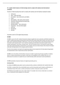
Scales
Although BS 8888 recognizes that standardization of scales isn’t as significant for CAD as it is for mechanical
drawings, the table below sets out the scales traditionally used for technical drawings.
We can see that the table is divided into two sections – enlargement scales that essentially make the object in the
drawing visually bigger, and reduction scales that display the objects as smaller.
BS 8888 notes that a 1:1 scale must always be used with 3D models produced in CAD.
Number formats
BS 8888 calls for the use of commas as opposed to full stops when writing decimals. Moreover, decimal numbers
lesser than 1 must have a 0 in front of the comma. We also ought to omit trailing zeros.
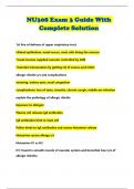
Lettering
BS 8888 refers us to BS EN ISO 3098 (which specifies the general requirements for lettering in technical drawings
but also includes part specific to CAD, such as the lettering of the Latin alphabet, numerals and marks in CAD) for
most lettering standards; however, it provides us with a handy table of preferred (advised) letter heights and
widths for specific sheet sizes.
standards.
Features of CAD drawings that need to comply with national and international standards include:
CAD layers
Lines – types and sizes
Annotation—text, dimensions and tables
Scales
File handling – file naming, data transfer
Geometric dimensioning and tolerancing
Geometric quality
Drawing sheets – sizes and layouts
Projections – first and third angles
Lettering
Numbering
Symbols
Standards used for CAD engineering drawings:
BS 8888
BS 8888 is a part of the UK’s national framework making it arguably the most commonly used British standard. It is
used for engineering drawings and geometrical tolerancing and includes details like the types and sized of nuts and
bolts used in engineering drawings. Furthermore, it also covers the requirements for the technical products specs
of products and component parts. It was created by combining all international standards needed to devise
product specifications, also known as product specs. The aim of products specs is to provide the product design
team with enough information to allow them to successfully create new product features that enhance the design
and match the expectations of the company and the customer.
The aim of the standard is to help the UK engineering industry move towards the ISO (International Organization
for Standarization) system of geometrical product specification.
BS 8888 covers all symbols and information necessary to include in engineering drawings regardless of whether
they are created manually (drawn by hand) or with CAD or 3D modelling as well as whether they are 2 or 3
dimensional. Its purpose is to explain the way in which drawings outline and present certain specifications.
BS 8888 standardizes important features of engineering drawing such as:
Drawing sheets
According to BS 8888 drawing sheets must be produced with accordance to BS EN ISO 5457 and BS EN ISO 7200.
ISO 7200 is a standard that sets out data fields (spaces used for storing data) used in headers and title blocks. It
standardizes features like names, contents and maximum number of characters used for each field.
ISO 7200 discusses possible issues such as data transfer. For example, how to move certain data in an ordered
form or sharing only certain segments of a document.
, The standard prioritized consistency and structure by guiding the user through how one should sort items by
characteristics into classes and subclasses.
ISO 5457 treats about the sizes and layouts of drawing sheets, including borders, trimming marks and frames. It
also provides a guide to the size system of drawing sheets as well as title blocks. Moreover, it also provides
examples of drawing sheets of varying sizes (from A0 to A4).
Line types and line widths
BS 8888 refers to BS EN ISO 128 when it comes to the line types and sizes. ISO 128 will be discussed in greater
detailed further down.
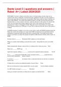
Scales
Although BS 8888 recognizes that standardization of scales isn’t as significant for CAD as it is for mechanical
drawings, the table below sets out the scales traditionally used for technical drawings.
We can see that the table is divided into two sections – enlargement scales that essentially make the object in the
drawing visually bigger, and reduction scales that display the objects as smaller.
BS 8888 notes that a 1:1 scale must always be used with 3D models produced in CAD.
Number formats
BS 8888 calls for the use of commas as opposed to full stops when writing decimals. Moreover, decimal numbers
lesser than 1 must have a 0 in front of the comma. We also ought to omit trailing zeros.
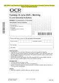
Lettering
BS 8888 refers us to BS EN ISO 3098 (which specifies the general requirements for lettering in technical drawings
but also includes part specific to CAD, such as the lettering of the Latin alphabet, numerals and marks in CAD) for
most lettering standards; however, it provides us with a handy table of preferred (advised) letter heights and
widths for specific sheet sizes.