ITEM: DESIGN OF ISOLATED FOOTING Design: ELS Date: 01/25/2021
PART: FTG-01 Check: RRE Date:
1.0 DESIGN OF ISOLATED FOOTING
1.1 References:
1.1.1 Building Code Requirements for Structural Concrete, ACI-318-19
1.1.2 National Structural Code of the Philippines, NSCP 2015
1.1.3 Control of Cracking of Concrete Structures, ACI 224R-01
1.2 Material Specifications and Constants
1.2.1 Concrete
Type of Concrete = Normal-weight
Concrete Compressive Strength f'c = 28 MPa
Unit Weight of Concrete δc = 24 kN/m3
Concrete Cover, cc
Top cctop = 75 mm
Bottom ccbot = 75 mm
Side ccside = 75 mm
Reduction Factor for Moment φf = 0.90
Reduction Factor for Shear φv = 0.75
Modulus of Elasticity of Concrete Ec = 24870.06 MPa
Beta 1 β1 = 0.85
Modification Factor λ = 1.00
1.2.2 Reinforcing Steel
Deformed Bars fy (MPa) ρmax ρmin ρmin,temp
12mm & Smaller 276 0.0377 0.0051 0.0020
16mm & Larger 414 0.0217 0.0034 0.0020
Modulus of Elasticity of Steel Es = 200000 MPa
Modular Ratio n = 8.04
1.2.3 Soil Properties
Allowable Gross Soil Bearing Capacity Qall = 250 kPa *Service
Allowable Gross Soil Bearing Capacity Qall = 325 kPa *Ultimate (x 1.3)
Allowable Net Soil Bearing Pressure qnet = 225 kPa *Service
Allowable Net Soil Bearing Pressure qnet = 300 kPa *Ultimate (x 1.3)
Unit Weight of Soil δs = 20 kN/m3
Friction Factor m= 0.3
Factor of Safety against Sliding FSS = 1.5
Factor of Safety against Overturning FSO = 1.5
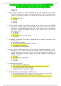
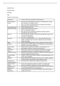
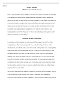
1.3 Geometry and Sections
Type of Footing = Eccentric
Eccentricity e = 0 mm
xx
Footing Width B = 1000 mm
Footing Length L = 1000 mm
Footing Thickness t = 400 mm
Depth of Bottom of Footing from FGL Df = 1200 mm xy Y
Column Width along X Cx = 300 mm
xx
Column Width along Y Cy = 300 mm
Cantilever Width Xx = 350 mm X
Cantilever Length Xy = 350 mm
,ITEM: DESIGN OF ISOLATED FOOTING Design: ELS Date: 01/25/2021
PART: FTG-01 Check: RRE Date:
Thickness of Soil above Top of Footing tsoil = 800 mm
Ratio of Length to Width β = 1.00
1.3 Loads and Load Combinations
1.3.1 Loads
(Reactions from the Loads applied for the Whole Structure STAAD file- See Section 1.4)
1.3.2 Load Combinations
Service Ultimate
1.00 DL 1.40 DL
1.00 DL + 1.00 SDL + 1.00 LL 1.20 DL + 1.20 SDL + 1.60 LL + 0.50 Lr
1.00 DL + Lr 1.20 DL + 1.60 LL
1.00 DL + 0.75LL + 0.75Lr 1.20 DL + 1.60 Lr + 1.00 LL
(1.00 + Ev) DL + 0.70 (SPECX + 0.3SPECY) 1.20 DL + 1.00 LL + 0.50 Lr
(1.00 + Ev) DL + 0.70 (0.3SPECX + SPECY) (1.20 + Ev) DL + 1.00LL + (SPECX + 0.3SPECY)
(1.00 + Ev) DL + 0.525 (SPECX + 0.3SPECY)+ 0.75LL + 0.75Lr (1.20 + Ev) DL + 1.00LL + (0.3SPECX + SPECY)
(1.00 + Ev) DL + 0.525 (0.3SPECX + SPECY)+ 0.75LL + 0.75Lr (0.90 - Ev) DL + (SPECX + 0.3SPECY)
(0.60 - Ev) DL + 0.70 (SPECX + 0.3SPECY) (0.90 - Ev) DL + (0.3SPECX + SPECY)
(0.60 - Ev) DL + 0.70 (0.3SPECX + SPECY)
1.4 Design Forces (STAADPro Analysis)
Summary:
qmax FSS-max FSO-max
For Size Check:
(kPa) - -
Service Loads Without Earthquake: 148.67 1.52 4.11
Service Loads With Earthquake: 148.67 1.52 4.11
Max Mux Max Muy Vu
For Reinforcements:
(kN-m) (kN-m) (kN)
Ultimate Loads With Earthquake: 19.84 19.84 33.70 bo = 2404 mm
1.5 Design of Size and Reinforcements
1.5.1 Check for Footing Size
Max qact FSS-max FSO-max
For Size Check:
(kPa) - -
Service Loads Without Earthquake: 148.67 1.52 4.11 OKAY
Service Loads With Earthquake: 148.67 1.52 4.11 OKAY
, ITEM: DESIGN OF ISOLATED FOOTING Design: ELS Date: 01/25/2021
PART: FTG-01 Check: RRE Date:
1.5.2 Design for Flexure Reinforcement
Orientation Mux = Transverse bars Muy = Longitudinal bars b = 1000 mm
Top bars Bottom bars
Flexure
reinforcement Longitudinal Transverse Longitudinal Transverse
Mu (kN/m/m) 0 0 20 20
Bar size (mm) 0 0 16 16
Bundle of 0 0 1 1
h (mm) 400 400
d (mm) 317.00 301.00
Rn 0.21932 0.24326
ρreq'd 0.00053 0.00059
ρuse 0.00071 0.00079
sreq'd 893.80 848.25
smax 251.33 251.33
Use S 250 250
MS (kN/m/m) 18 18
fs (MPa) 71.43 75.23
smax(serv) 450.00 450.00
Remarks OK OK
1.5.3 Design for Shear Reinforcement
Punching Shear
Location of Column = Interior Column
Constant for Vc αs = 40
Shear from Ultimate Loads Vu = 33.70 kN
Concrete Shear Capacity ΦVc = 972.85 kN
Required Steel Shear Strength ΦVs = 0.00 kN , No Shear Reinforcements Required
Shear Reinforcements
Number of Legs N = 2
Shear Reinforcement Diameter øs = 12 mm
Spacing of Ties sties = 0 mm
Min. Area of Shear Reinf. Avmin = 0.00 mm2 ,
1.5.4 Design for Development Length of Bars
Top bars Bottom bars
Development
Length Longitudinal Transverse Longitudinal Transverse
Bar size (mm) 0 0 16 16
ℓd-min - C (mm) 200 200 200 200
ℓdmin - T (mm) 300 300 200 200
ℓdreq'd (mm) 0 0 600 600
Use ℓd (mm) 0 0 0 0
PART: FTG-01 Check: RRE Date:
1.0 DESIGN OF ISOLATED FOOTING
1.1 References:
1.1.1 Building Code Requirements for Structural Concrete, ACI-318-19
1.1.2 National Structural Code of the Philippines, NSCP 2015
1.1.3 Control of Cracking of Concrete Structures, ACI 224R-01
1.2 Material Specifications and Constants
1.2.1 Concrete
Type of Concrete = Normal-weight
Concrete Compressive Strength f'c = 28 MPa
Unit Weight of Concrete δc = 24 kN/m3
Concrete Cover, cc
Top cctop = 75 mm
Bottom ccbot = 75 mm
Side ccside = 75 mm
Reduction Factor for Moment φf = 0.90
Reduction Factor for Shear φv = 0.75
Modulus of Elasticity of Concrete Ec = 24870.06 MPa
Beta 1 β1 = 0.85
Modification Factor λ = 1.00
1.2.2 Reinforcing Steel
Deformed Bars fy (MPa) ρmax ρmin ρmin,temp
12mm & Smaller 276 0.0377 0.0051 0.0020
16mm & Larger 414 0.0217 0.0034 0.0020
Modulus of Elasticity of Steel Es = 200000 MPa
Modular Ratio n = 8.04
1.2.3 Soil Properties
Allowable Gross Soil Bearing Capacity Qall = 250 kPa *Service
Allowable Gross Soil Bearing Capacity Qall = 325 kPa *Ultimate (x 1.3)
Allowable Net Soil Bearing Pressure qnet = 225 kPa *Service
Allowable Net Soil Bearing Pressure qnet = 300 kPa *Ultimate (x 1.3)
Unit Weight of Soil δs = 20 kN/m3
Friction Factor m= 0.3
Factor of Safety against Sliding FSS = 1.5
Factor of Safety against Overturning FSO = 1.5
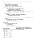
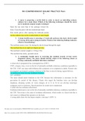
1.3 Geometry and Sections
Type of Footing = Eccentric
Eccentricity e = 0 mm
xx
Footing Width B = 1000 mm
Footing Length L = 1000 mm
Footing Thickness t = 400 mm
Depth of Bottom of Footing from FGL Df = 1200 mm xy Y
Column Width along X Cx = 300 mm
xx
Column Width along Y Cy = 300 mm
Cantilever Width Xx = 350 mm X
Cantilever Length Xy = 350 mm
,ITEM: DESIGN OF ISOLATED FOOTING Design: ELS Date: 01/25/2021
PART: FTG-01 Check: RRE Date:
Thickness of Soil above Top of Footing tsoil = 800 mm
Ratio of Length to Width β = 1.00
1.3 Loads and Load Combinations
1.3.1 Loads
(Reactions from the Loads applied for the Whole Structure STAAD file- See Section 1.4)
1.3.2 Load Combinations
Service Ultimate
1.00 DL 1.40 DL
1.00 DL + 1.00 SDL + 1.00 LL 1.20 DL + 1.20 SDL + 1.60 LL + 0.50 Lr
1.00 DL + Lr 1.20 DL + 1.60 LL
1.00 DL + 0.75LL + 0.75Lr 1.20 DL + 1.60 Lr + 1.00 LL
(1.00 + Ev) DL + 0.70 (SPECX + 0.3SPECY) 1.20 DL + 1.00 LL + 0.50 Lr
(1.00 + Ev) DL + 0.70 (0.3SPECX + SPECY) (1.20 + Ev) DL + 1.00LL + (SPECX + 0.3SPECY)
(1.00 + Ev) DL + 0.525 (SPECX + 0.3SPECY)+ 0.75LL + 0.75Lr (1.20 + Ev) DL + 1.00LL + (0.3SPECX + SPECY)
(1.00 + Ev) DL + 0.525 (0.3SPECX + SPECY)+ 0.75LL + 0.75Lr (0.90 - Ev) DL + (SPECX + 0.3SPECY)
(0.60 - Ev) DL + 0.70 (SPECX + 0.3SPECY) (0.90 - Ev) DL + (0.3SPECX + SPECY)
(0.60 - Ev) DL + 0.70 (0.3SPECX + SPECY)
1.4 Design Forces (STAADPro Analysis)
Summary:
qmax FSS-max FSO-max
For Size Check:
(kPa) - -
Service Loads Without Earthquake: 148.67 1.52 4.11
Service Loads With Earthquake: 148.67 1.52 4.11
Max Mux Max Muy Vu
For Reinforcements:
(kN-m) (kN-m) (kN)
Ultimate Loads With Earthquake: 19.84 19.84 33.70 bo = 2404 mm
1.5 Design of Size and Reinforcements
1.5.1 Check for Footing Size
Max qact FSS-max FSO-max
For Size Check:
(kPa) - -
Service Loads Without Earthquake: 148.67 1.52 4.11 OKAY
Service Loads With Earthquake: 148.67 1.52 4.11 OKAY
, ITEM: DESIGN OF ISOLATED FOOTING Design: ELS Date: 01/25/2021
PART: FTG-01 Check: RRE Date:
1.5.2 Design for Flexure Reinforcement
Orientation Mux = Transverse bars Muy = Longitudinal bars b = 1000 mm
Top bars Bottom bars
Flexure
reinforcement Longitudinal Transverse Longitudinal Transverse
Mu (kN/m/m) 0 0 20 20
Bar size (mm) 0 0 16 16
Bundle of 0 0 1 1
h (mm) 400 400
d (mm) 317.00 301.00
Rn 0.21932 0.24326
ρreq'd 0.00053 0.00059
ρuse 0.00071 0.00079
sreq'd 893.80 848.25
smax 251.33 251.33
Use S 250 250
MS (kN/m/m) 18 18
fs (MPa) 71.43 75.23
smax(serv) 450.00 450.00
Remarks OK OK
1.5.3 Design for Shear Reinforcement
Punching Shear
Location of Column = Interior Column
Constant for Vc αs = 40
Shear from Ultimate Loads Vu = 33.70 kN
Concrete Shear Capacity ΦVc = 972.85 kN
Required Steel Shear Strength ΦVs = 0.00 kN , No Shear Reinforcements Required
Shear Reinforcements
Number of Legs N = 2
Shear Reinforcement Diameter øs = 12 mm
Spacing of Ties sties = 0 mm
Min. Area of Shear Reinf. Avmin = 0.00 mm2 ,
1.5.4 Design for Development Length of Bars
Top bars Bottom bars
Development
Length Longitudinal Transverse Longitudinal Transverse
Bar size (mm) 0 0 16 16
ℓd-min - C (mm) 200 200 200 200
ℓdmin - T (mm) 300 300 200 200
ℓdreq'd (mm) 0 0 600 600
Use ℓd (mm) 0 0 0 0