QN [85]
A power processor is required to feed an application at a voltage of 60 VDC.
Galvanic isolation is required and a full-bridge DC-DC converter with
transformer isolation is employed to realise the interface. The switching
frequency is 50 kHz and a surface temperature of 1000C is to be assumed. Input
DC voltage is obtained by rectifying the available AC supply of 220V, 50 Hz.
The peak-peak ripple in the input DC voltage should not exceed 2% of the peak
DC voltage.
The secondary winding is centre-tapped and an LC filter is connected at the
output terminal of the high frequency rectifier. It keeps the peak-peak output
current ripple less than 20% of the nominal load current while the peak-peak
output ripple voltage is less than 2% of the nominal output voltage. Rated load
power is 3000 W.
The high-frequency rectifier diodes have forward voltage drop of 1.0 V. The
full-bridge high-frequency inverter used to convert the input DC voltage into a
high-frequency AC waveform employs semiconductor devices with a voltage
drop of 1.5 V when conducting. The output filter inductor has a series resistance
of 10 m and the semiconductor devices have rise- and fall-times of 200 ns with
a tolerance of 15%.
Stating any assumptions made, determine:
i. Practical waveform duty ratio and the turns-ratio [6]
max 10.954
choose
max 0.954
vˆ pri 305.016V
I L , ave 50 A
vˆsec 64.465V
n 4.7315
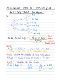
ii. Sketch the input current waveform, the high-frequency inverter switches
current and voltage waveforms. Graduate all axes indicating time and
magnitude information [18]
1
, iii. Determine the capacitance and inductance of output filter components to
meet specifications [5]
Lo 2.829H
Co 10.42 F
iv. Determine practical values of voltage and current ratings for high-
frequency inverter semiconductor devices[6]
Vsw,block 306.516V
Vswitch , rated 459.774V 613.032V
I sw, rms 7.31A
I sw, rating 10.965 14.62 A
2
A power processor is required to feed an application at a voltage of 60 VDC.
Galvanic isolation is required and a full-bridge DC-DC converter with
transformer isolation is employed to realise the interface. The switching
frequency is 50 kHz and a surface temperature of 1000C is to be assumed. Input
DC voltage is obtained by rectifying the available AC supply of 220V, 50 Hz.
The peak-peak ripple in the input DC voltage should not exceed 2% of the peak
DC voltage.
The secondary winding is centre-tapped and an LC filter is connected at the
output terminal of the high frequency rectifier. It keeps the peak-peak output
current ripple less than 20% of the nominal load current while the peak-peak
output ripple voltage is less than 2% of the nominal output voltage. Rated load
power is 3000 W.
The high-frequency rectifier diodes have forward voltage drop of 1.0 V. The
full-bridge high-frequency inverter used to convert the input DC voltage into a
high-frequency AC waveform employs semiconductor devices with a voltage
drop of 1.5 V when conducting. The output filter inductor has a series resistance
of 10 m and the semiconductor devices have rise- and fall-times of 200 ns with
a tolerance of 15%.
Stating any assumptions made, determine:
i. Practical waveform duty ratio and the turns-ratio [6]
max 10.954
choose
max 0.954
vˆ pri 305.016V
I L , ave 50 A
vˆsec 64.465V
n 4.7315
ii. Sketch the input current waveform, the high-frequency inverter switches
current and voltage waveforms. Graduate all axes indicating time and
magnitude information [18]
1
, iii. Determine the capacitance and inductance of output filter components to
meet specifications [5]
Lo 2.829H
Co 10.42 F
iv. Determine practical values of voltage and current ratings for high-
frequency inverter semiconductor devices[6]
Vsw,block 306.516V
Vswitch , rated 459.774V 613.032V
I sw, rms 7.31A
I sw, rating 10.965 14.62 A
2