Analog Electronics
1. To prevent a DC return between source and
load, it is necessary to use
A. resistor between source and load
B. inductor between source and load
C. capacitor between source and load
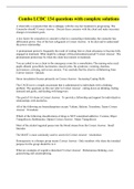
A. D2 only B. D1 only
D. either (a) or (b)
C. Both D1 and D2 D. Neither D1 nor D2
Capacitor offers infinite impedance to DC.
D1 will conduct and the output voltage will be
2. For a base current of 10 μA, what is the value of about 7 V. Therefore D2 will be reverse biased and
collector current in common emitter if βdc = 100 5. A half wave diode circuit using ideal diode has will not conduct.
A. 10 μA B. 100 μA an input voltage 20 sin ωt volts. Then average and 8. The load impedance ZL of a CE amplifier has R
rms values of output voltage are and L in series. The phase difference between
C. 1 mA D. 10 mA
A. and 10 V B. and 10 V output and input will be
IC = 10 x 100 μA = 1 mA.
C. and 5 V D. and 5 V A. 180°
3. Which of the following oscillators is suitable for
B. 0
frequencies in the range of mega hertz?
and VC = 0.5 x 20 = 10 V. C. more than 90° but less than 180°
A. RC phase shift B. Wien bridge
6. An RC coupled amplifier has an open loop gain D. more than 180° but less than 270°
C. Hartley D. Both (a) and (c)
of 200 and a lower cutoff frequency of 50 Hz. If
It is 180° for purely resistive load and between
Only LC oscillators are suitable for MHz range. negative feedback with β = 0.1 is used, the lower
180° and 270° for R-L load.
cut off frequency will be
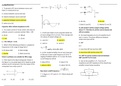
4. If the input to the ideal comparator shown in
9. Gain of the amplifier is 'A'. Then the I/P
the figure is a sinusoidal signal of 8 V (peak to peak) A. about 50 Hz B. about 5 Hz
impedance and O/P impedance of the closed loop
without any DC component, then the output of the
C. about 2.38 Hz D. about 70.5 Hz amplifier shown below would be
comparator has a duty cycle of
New lower cutoff frequency = .
7. In figure v1 = 8 V and v2 = 4 V. Which diode will
conduct?
A. 1/2 B. 1/3 C. 1/6 D. 1/12
, A. 9.3 V and 1.98 mA respectively
A.
B. 4.6 V and 1.98 mA respectively
A = - 1000, β = -0.1 .
B. C. 9.3 V and 0.02 mA respectively
11. In figure The minimum and maximum load
currents are D. 4.6 V and 0.02 mA respectively
C.
D.
By using Miller theorem circuit can be
redrawn as VC = 20 - 1.98 x 10-3 x 5.4 x 103 9.3 V.
A. 0 and 60 mA 13. The input impedance of op-amp circuit of
figure is
B. 0 and 120 mA
C. 10 mA and 60 mA
D. 10 mA and 120 mA
. When RL = ∞, IL = 0,
10. If an amplifier with gain of - 1000 and feedback
factor β = - 0.1 had a gain change of 20% due to When RL = 100 Ω, or 120 mA. A. 120 k ohm
temperature, the change in gain of the feedback
amplifier would be 12. In figure, VEB = 0.6 V, β = 99. Then VC B. 110 k ohm
and IC are
A. 10% B. 5% C. 0.2% D. 0.01%
C. infinity
D. 10 k ohm
Due to the presence of virtual ground at
As we know, Gain with feedback input, the resistance in the series path of
input of inverting amplifier is input
impedance.
, 14. In a BJT circuit a pnp transistor is replaced A. -100 V B. -100 mV 19. An amplifier has a large ac input signal.
by npn transistor. To analyse the new circuit The clipping occurs on both the peaks. The
C. 10 V D. 10 mV output voltage will be nearly a
A. all calculations done earlier have to be
repeated Input to non-inverting op-amp is -10 x 10-6 x A. sine wave B. square wave
103 = -10 mV. Therefore output =
B. replace all calculated voltages by reverse C. triangular wave D. (a) or (c)
values
= -100 mV. When a sinusoidal voltage is clipped on both
C. replace all calculated currents by reverse sides it resembles a square wave.
values 17. In a CE amplifier the input impedance is
equal to the ratio of 20. The transistor of following figure in Si
D. replace all calculated voltages and currents diode with a base current of 40 μA and ICBO =
by reverse values A. ac base voltage to ac base current 0, if VBB = 6V, RE = 2 kΩ and β = 90, IBQ =
20 μA then RB =
All voltages and currents have reverse B. ac base voltage to ac emitter current
polarity.
C. ac emitter voltage to ac collector current
15. To protect the diodes in a rectifier and
capacitor input filter circuit it is necessary to D. ac collector voltage to ac collector current
use
Input is applied to base with emitter
A. surge resistor B. surge inductor grounded. The input impedance is the ratio
of ac base voltage to ac base current.
C. surge capacitor D. both (a) and (b)
18. For a system to work, as oscillator the total A. 200 kΩ B. 265 kΩ
Resistor reduces surge current. phase shift of the loop gain must be equal to
C. 150 kΩ D. 100 kΩ
16. The output V0 in figure is A. 90° B. 45° C. 270° D. 360°
Gain of system with + ve feedback =
.
for oscillation 21. In the amplifier circuit of figure hfe = 100
and hie = 1000 Ω. The voltage gain of amplifier
but V0 ≠ 0 is about
so, that 1 - AB = 0 AB = 1 ∠0° or 360°.
1. To prevent a DC return between source and
load, it is necessary to use
A. resistor between source and load
B. inductor between source and load
C. capacitor between source and load
A. D2 only B. D1 only
D. either (a) or (b)
C. Both D1 and D2 D. Neither D1 nor D2
Capacitor offers infinite impedance to DC.
D1 will conduct and the output voltage will be
2. For a base current of 10 μA, what is the value of about 7 V. Therefore D2 will be reverse biased and
collector current in common emitter if βdc = 100 5. A half wave diode circuit using ideal diode has will not conduct.
A. 10 μA B. 100 μA an input voltage 20 sin ωt volts. Then average and 8. The load impedance ZL of a CE amplifier has R
rms values of output voltage are and L in series. The phase difference between
C. 1 mA D. 10 mA
A. and 10 V B. and 10 V output and input will be
IC = 10 x 100 μA = 1 mA.
C. and 5 V D. and 5 V A. 180°
3. Which of the following oscillators is suitable for
B. 0
frequencies in the range of mega hertz?
and VC = 0.5 x 20 = 10 V. C. more than 90° but less than 180°
A. RC phase shift B. Wien bridge
6. An RC coupled amplifier has an open loop gain D. more than 180° but less than 270°
C. Hartley D. Both (a) and (c)
of 200 and a lower cutoff frequency of 50 Hz. If
It is 180° for purely resistive load and between
Only LC oscillators are suitable for MHz range. negative feedback with β = 0.1 is used, the lower
180° and 270° for R-L load.
cut off frequency will be
4. If the input to the ideal comparator shown in
9. Gain of the amplifier is 'A'. Then the I/P
the figure is a sinusoidal signal of 8 V (peak to peak) A. about 50 Hz B. about 5 Hz
impedance and O/P impedance of the closed loop
without any DC component, then the output of the
C. about 2.38 Hz D. about 70.5 Hz amplifier shown below would be
comparator has a duty cycle of
New lower cutoff frequency = .
7. In figure v1 = 8 V and v2 = 4 V. Which diode will
conduct?
A. 1/2 B. 1/3 C. 1/6 D. 1/12
, A. 9.3 V and 1.98 mA respectively
A.
B. 4.6 V and 1.98 mA respectively
A = - 1000, β = -0.1 .
B. C. 9.3 V and 0.02 mA respectively
11. In figure The minimum and maximum load
currents are D. 4.6 V and 0.02 mA respectively
C.
D.
By using Miller theorem circuit can be
redrawn as VC = 20 - 1.98 x 10-3 x 5.4 x 103 9.3 V.
A. 0 and 60 mA 13. The input impedance of op-amp circuit of
figure is
B. 0 and 120 mA
C. 10 mA and 60 mA
D. 10 mA and 120 mA
. When RL = ∞, IL = 0,
10. If an amplifier with gain of - 1000 and feedback
factor β = - 0.1 had a gain change of 20% due to When RL = 100 Ω, or 120 mA. A. 120 k ohm
temperature, the change in gain of the feedback
amplifier would be 12. In figure, VEB = 0.6 V, β = 99. Then VC B. 110 k ohm
and IC are
A. 10% B. 5% C. 0.2% D. 0.01%
C. infinity
D. 10 k ohm
Due to the presence of virtual ground at
As we know, Gain with feedback input, the resistance in the series path of
input of inverting amplifier is input
impedance.
, 14. In a BJT circuit a pnp transistor is replaced A. -100 V B. -100 mV 19. An amplifier has a large ac input signal.
by npn transistor. To analyse the new circuit The clipping occurs on both the peaks. The
C. 10 V D. 10 mV output voltage will be nearly a
A. all calculations done earlier have to be
repeated Input to non-inverting op-amp is -10 x 10-6 x A. sine wave B. square wave
103 = -10 mV. Therefore output =
B. replace all calculated voltages by reverse C. triangular wave D. (a) or (c)
values
= -100 mV. When a sinusoidal voltage is clipped on both
C. replace all calculated currents by reverse sides it resembles a square wave.
values 17. In a CE amplifier the input impedance is
equal to the ratio of 20. The transistor of following figure in Si
D. replace all calculated voltages and currents diode with a base current of 40 μA and ICBO =
by reverse values A. ac base voltage to ac base current 0, if VBB = 6V, RE = 2 kΩ and β = 90, IBQ =
20 μA then RB =
All voltages and currents have reverse B. ac base voltage to ac emitter current
polarity.
C. ac emitter voltage to ac collector current
15. To protect the diodes in a rectifier and
capacitor input filter circuit it is necessary to D. ac collector voltage to ac collector current
use
Input is applied to base with emitter
A. surge resistor B. surge inductor grounded. The input impedance is the ratio
of ac base voltage to ac base current.
C. surge capacitor D. both (a) and (b)
18. For a system to work, as oscillator the total A. 200 kΩ B. 265 kΩ
Resistor reduces surge current. phase shift of the loop gain must be equal to
C. 150 kΩ D. 100 kΩ
16. The output V0 in figure is A. 90° B. 45° C. 270° D. 360°
Gain of system with + ve feedback =
.
for oscillation 21. In the amplifier circuit of figure hfe = 100
and hie = 1000 Ω. The voltage gain of amplifier
but V0 ≠ 0 is about
so, that 1 - AB = 0 AB = 1 ∠0° or 360°.