Zeyn Mahomed Grade 10 2020
LU6 - Boolean Logic
1. Introduction
Boolean Logic ● Single switch is known as a bit
● TRUE is represented in a bit with a 1
● FALSE is represented in a bit with a 0
2. Boolean Logical Statements
Adapted from outside sources as well
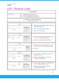
AND
● Electronic Circuit that gives high output (1) if
all its inputs are high
● A dot (.) is used to represent AND
● (A.B) or is omitted (AB)
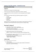
OR
● Electronic Circuit that gives high output (1) if
one or more of its inputs are high
● A plus (+) is used to represent OR (A+B)
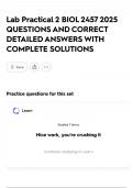
NOT
● Electronic Circuit that produces an inverted
version of the input as its output (inverter)
● (A’) or (Ā)
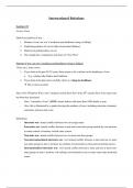
NAND
● NOT-AND gate - outputs are high if any of
the inputs are low
● Symbol - AND gate with a small circle
(inversion) on the output
NOR ● NOT-OR gate - outputs of all NOR gates are
low if any of the inputs are high
● Symbol - OR gate with a small circle
(inversion) on the output
27
LU6 - Boolean Logic
1. Introduction
Boolean Logic ● Single switch is known as a bit
● TRUE is represented in a bit with a 1
● FALSE is represented in a bit with a 0
2. Boolean Logical Statements
Adapted from outside sources as well
AND
● Electronic Circuit that gives high output (1) if
all its inputs are high
● A dot (.) is used to represent AND
● (A.B) or is omitted (AB)
OR
● Electronic Circuit that gives high output (1) if
one or more of its inputs are high
● A plus (+) is used to represent OR (A+B)
NOT
● Electronic Circuit that produces an inverted
version of the input as its output (inverter)
● (A’) or (Ā)
NAND
● NOT-AND gate - outputs are high if any of
the inputs are low
● Symbol - AND gate with a small circle
(inversion) on the output
NOR ● NOT-OR gate - outputs of all NOR gates are
low if any of the inputs are high
● Symbol - OR gate with a small circle
(inversion) on the output
27