School of Engineering Technology
EET230
Hendry Sumo Jr Digital Systems II
04/13/1015 Lab 1 Activity - Flip Flops
Objectives
Investigate the operation of various configurations of Flip-Flops
Submission
Complete all truth tables, insert screenshots (with date/time stamps), and answer all questions.
Add your answers to this document and submit.
A separate lab report is not required for this activity.
Video Resources:
Latches & Flip-Flops
Introduction
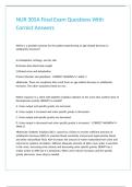
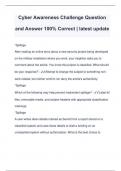
A latch is a type of bistable logic device or multivibrator. An active-HIGH input S-R (SET-
RESET) latch is formed with two cross-coupled NOR gates, as shown in Figure 7–1(a); an
active-LOW input latch is formed with two cross-coupled NAND gates, as shown in Figure 7–
1(b).
Notice that the output of each gate is connected to an input of the opposite gate.
This produces the regenerative feedback that is characteristic of all latches and flip-flops.
1
, School of Engineering Technology
Abstract
This lab explores the fundamental concepts and functionality of key sequential logic components,
including the S-R latch, JK flip-flop, and D flip-flop. Using Multisim, circuits were designed and
simulated to analyze the behavior of each device. The JK flip-flop was evaluated through its truth table,
showcasing its state storage and toggling capabilities. The D flip-flop was tested for its ability to capture
and transfer data on the clock edge. Additionally, an S-R latch was built using NOR gates to demonstrate
its bistable nature. The simulation results validated the expected performance of each component,
emphasizing their critical role in digital logic and sequential circuit design.
Parts List
Miscellaneous: Components Measuring Instruments:
1. SN74LS76 Dual JK Flip LEDs
Multisim© Software Flop Logic Probe
2. 74LS74 Dual D Flip Flop
Refer to the ICs datasheets in your course shell for a complete understanding of their characteristics.
Circuit Construction:
Download and open the Multisim file for Lab 1 from your course shell.
The Multisim file includes all parts of the lab with all needed components.
2
EET230
Hendry Sumo Jr Digital Systems II
04/13/1015 Lab 1 Activity - Flip Flops
Objectives
Investigate the operation of various configurations of Flip-Flops
Submission
Complete all truth tables, insert screenshots (with date/time stamps), and answer all questions.
Add your answers to this document and submit.
A separate lab report is not required for this activity.
Video Resources:
Latches & Flip-Flops
Introduction
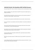
A latch is a type of bistable logic device or multivibrator. An active-HIGH input S-R (SET-
RESET) latch is formed with two cross-coupled NOR gates, as shown in Figure 7–1(a); an
active-LOW input latch is formed with two cross-coupled NAND gates, as shown in Figure 7–
1(b).
Notice that the output of each gate is connected to an input of the opposite gate.
This produces the regenerative feedback that is characteristic of all latches and flip-flops.
1
, School of Engineering Technology
Abstract
This lab explores the fundamental concepts and functionality of key sequential logic components,
including the S-R latch, JK flip-flop, and D flip-flop. Using Multisim, circuits were designed and
simulated to analyze the behavior of each device. The JK flip-flop was evaluated through its truth table,
showcasing its state storage and toggling capabilities. The D flip-flop was tested for its ability to capture
and transfer data on the clock edge. Additionally, an S-R latch was built using NOR gates to demonstrate
its bistable nature. The simulation results validated the expected performance of each component,
emphasizing their critical role in digital logic and sequential circuit design.
Parts List
Miscellaneous: Components Measuring Instruments:
1. SN74LS76 Dual JK Flip LEDs
Multisim© Software Flop Logic Probe
2. 74LS74 Dual D Flip Flop
Refer to the ICs datasheets in your course shell for a complete understanding of their characteristics.
Circuit Construction:
Download and open the Multisim file for Lab 1 from your course shell.
The Multisim file includes all parts of the lab with all needed components.
2