LC PHYSICS DEMONSTRATION
EXPERIMENTS
TO DEMONSTRATE THE LAWS OF REFLECTION.
Set up the equipment shown in FIG. 2.7 (page 9).
Adjust the ray box until it is producing a very narrow beam, i.e. a ray.
Place the mirror on the drawing paper and mark its position with a pencil.
Shine the ray onto the mirror. With a pencil mark the direction of the ray
before it strikes the mirror and after it reflects from the mirror.
Remove the mirror. Draw in the normal at the point of incidence, the
incident ray and the reflected ray.
With a protractor, measure the angle of incidence (i) and the angle of
reflection (r).
Record these values.
Repeat the experiment for different values of the angle of incidence.
Result
Within the limits of experimental error it will be found that the angle of
incidence is equal to the angle of reflection, thus showing Law 2.
The reflected ray will be travelling parallel to the paper, i.e. it will
not be heading up from the paper or heading into the paper. It will be in
the same plane as the incident ray and the normal, thus showing Law 1.
TO LOCATE AN IMAGE IN A PLANE MIRROR BY THE METHOD OF NO
PARALLAX.
Method
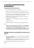
Set up the equipment shown in FIG. 2.15. A virtual image of the object pin
will be seen in the mirror.
Adjust the height of the search pin so that its tip is just above the top of
the mirror.
Looking towards the mirror and ignoring the object pin you should see: (i)
the image in the mirror, (ii) the search pin above the mirror.
Adjust the search pin until it appears to be in line with the image.
Fig. 2.15
, Move the search pin towards or away from the mirror until there is no
parallax between the image and the search pin.The search pin then points
out the position of the image.
Using a metre stick, measure the distance (u) from the object to the silver
of the mirror. Measure the distance (v) from the search pin to the silver of
the mirror (which is equal to the distance from the image to the mirror).
Result
Within the limits of experimental error u will be equal to v, thus verifying that the
image in a plane mirror is the same distance behind the mirror as the object in
front of the mirror.
TO DEMONSTRATE REFRACTION.
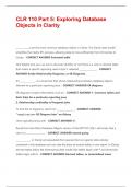
With the equipment in FIG. 4.3 adjust the ray box to produce a very narrow
beam, i.e. a ray.
Shine the ray onto one side of the glass block. Note how the ray bends on
entering the glass and bends again on leaving the block. Note that the ray
coming out of the glass block is parallel to the ray striking the block.
Shine the ray onto the glass block so that it strikes the block at right
angles. Note that the ray does not bend on entering the glass but simply
passes straight through.
Repeat the experiment for different angles of incidence.You will see that
the angle of refraction increases as the angle of incidence increases ( FIG.
4.4). If you measured the size of the angles you would see that they do not
increase proportionally.
Fig. 4.3
As the angle of incidence increases so does the angle of refraction, but they do not increase proportionally.
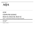
TO DEMONSTRATE TOTAL INTERNAL REFLECTION
Fig. 4.24
• Set up a ray box and a semicircular slab of glass as in FIG. 4.24(A).
• Starting with a small angle of incidence, slowly increase this angle.
• Soon the critical angle will be reached and the refracted ray skims along the flat face of the
glass. If the angle of incidence is then increased any further, the refracted ray suddenly jumps
from that shown in FIG. 4.24(B) to that in FIG. 4.24(C) to become the totally internally
reflected ray.
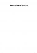
, TO FIND THE RESULTANT OF TWO FORCES.
Set up the equipment as in FIG. 8.14 using newton balances (spring
balances graduated in newtons).
Adjust the size and direction of the three forces until the knot in the thread
remains at rest.
If we want the resultant of the two forces F1 and F2, its magnitude is the
reading on the third balance (F3).The direction of the resultant is in the
opposite direction to F3.
Fig. 8.14
TO DEMONSTRATE THE PRINCIPLE OF ARCHIMEDES
In this experiment you will measure:
(i) the upthrust on a submerged object and
(ii) the weight of liquid it displaces.
The upthrust and the weight will be the same, thus verifying Archimedes’
Principle.
To Find the Upthrust
Fig. 10.9
On a spring balance, weigh an object that sinks in water ( FIG. 10.9).
Keeping the object on the balance, lower the object into a beaker of water
until it is completely submerged (FIG. 10.9).Take the reading on the
balance.
Subtract the two readings.The difference between the two readings is the
upthrust.
To Find the Weight of the Displaced Liquid
Fill an overflow can with water and allow it to settle.
Lower the object slowly into the can. Collect the water displaced in a
previously weighed beaker.
Weight the beaker and the water. By subtraction find the weight of the
displaced water.
Result
The upthrust and the weight of the displaced water will be the same, thus
verifying Archimedes’ Principle.
TO COMPARE THE RATES OF CONDUCTION THROUGH VARIOUS
SOLIDS.
1. Use the equipment in FIG. 15.9.
EXPERIMENTS
TO DEMONSTRATE THE LAWS OF REFLECTION.
Set up the equipment shown in FIG. 2.7 (page 9).
Adjust the ray box until it is producing a very narrow beam, i.e. a ray.
Place the mirror on the drawing paper and mark its position with a pencil.
Shine the ray onto the mirror. With a pencil mark the direction of the ray
before it strikes the mirror and after it reflects from the mirror.
Remove the mirror. Draw in the normal at the point of incidence, the
incident ray and the reflected ray.
With a protractor, measure the angle of incidence (i) and the angle of
reflection (r).
Record these values.
Repeat the experiment for different values of the angle of incidence.
Result
Within the limits of experimental error it will be found that the angle of
incidence is equal to the angle of reflection, thus showing Law 2.
The reflected ray will be travelling parallel to the paper, i.e. it will
not be heading up from the paper or heading into the paper. It will be in
the same plane as the incident ray and the normal, thus showing Law 1.
TO LOCATE AN IMAGE IN A PLANE MIRROR BY THE METHOD OF NO
PARALLAX.
Method
Set up the equipment shown in FIG. 2.15. A virtual image of the object pin
will be seen in the mirror.
Adjust the height of the search pin so that its tip is just above the top of
the mirror.
Looking towards the mirror and ignoring the object pin you should see: (i)
the image in the mirror, (ii) the search pin above the mirror.
Adjust the search pin until it appears to be in line with the image.
Fig. 2.15
, Move the search pin towards or away from the mirror until there is no
parallax between the image and the search pin.The search pin then points
out the position of the image.
Using a metre stick, measure the distance (u) from the object to the silver
of the mirror. Measure the distance (v) from the search pin to the silver of
the mirror (which is equal to the distance from the image to the mirror).
Result
Within the limits of experimental error u will be equal to v, thus verifying that the
image in a plane mirror is the same distance behind the mirror as the object in
front of the mirror.
TO DEMONSTRATE REFRACTION.
With the equipment in FIG. 4.3 adjust the ray box to produce a very narrow
beam, i.e. a ray.
Shine the ray onto one side of the glass block. Note how the ray bends on
entering the glass and bends again on leaving the block. Note that the ray
coming out of the glass block is parallel to the ray striking the block.
Shine the ray onto the glass block so that it strikes the block at right
angles. Note that the ray does not bend on entering the glass but simply
passes straight through.
Repeat the experiment for different angles of incidence.You will see that
the angle of refraction increases as the angle of incidence increases ( FIG.
4.4). If you measured the size of the angles you would see that they do not
increase proportionally.
Fig. 4.3
As the angle of incidence increases so does the angle of refraction, but they do not increase proportionally.
TO DEMONSTRATE TOTAL INTERNAL REFLECTION
Fig. 4.24
• Set up a ray box and a semicircular slab of glass as in FIG. 4.24(A).
• Starting with a small angle of incidence, slowly increase this angle.
• Soon the critical angle will be reached and the refracted ray skims along the flat face of the
glass. If the angle of incidence is then increased any further, the refracted ray suddenly jumps
from that shown in FIG. 4.24(B) to that in FIG. 4.24(C) to become the totally internally
reflected ray.
, TO FIND THE RESULTANT OF TWO FORCES.
Set up the equipment as in FIG. 8.14 using newton balances (spring
balances graduated in newtons).
Adjust the size and direction of the three forces until the knot in the thread
remains at rest.
If we want the resultant of the two forces F1 and F2, its magnitude is the
reading on the third balance (F3).The direction of the resultant is in the
opposite direction to F3.
Fig. 8.14
TO DEMONSTRATE THE PRINCIPLE OF ARCHIMEDES
In this experiment you will measure:
(i) the upthrust on a submerged object and
(ii) the weight of liquid it displaces.
The upthrust and the weight will be the same, thus verifying Archimedes’
Principle.
To Find the Upthrust
Fig. 10.9
On a spring balance, weigh an object that sinks in water ( FIG. 10.9).
Keeping the object on the balance, lower the object into a beaker of water
until it is completely submerged (FIG. 10.9).Take the reading on the
balance.
Subtract the two readings.The difference between the two readings is the
upthrust.
To Find the Weight of the Displaced Liquid
Fill an overflow can with water and allow it to settle.
Lower the object slowly into the can. Collect the water displaced in a
previously weighed beaker.
Weight the beaker and the water. By subtraction find the weight of the
displaced water.
Result
The upthrust and the weight of the displaced water will be the same, thus
verifying Archimedes’ Principle.
TO COMPARE THE RATES OF CONDUCTION THROUGH VARIOUS
SOLIDS.
1. Use the equipment in FIG. 15.9.