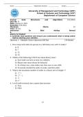
ENG 1450 Introduction to Electrical and Computer Engineering
Lab 1
Basic Circuit Concepts
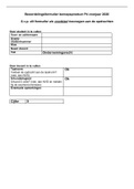
Name: _______________________________
Student Number: _______________________________
Lab Section: _______________________________
Instructor: _______________________________
Date: _______________________________
Did students clean-up after the lab? _________________________
TA signature
ENG 1450 - Lab 1 November 22, 2023-v1 Page 1
, Part A: Ohm’s Law
Equipment:
• Select 1,000 Ω resistors for these circuits.
1. Read the color code on the resistors to determine its rating. R = __________ ± _____ %
2. Measure the value of the resistor with the multimeter and calculate how this measured value
compares with the resistor color code.
Measured value: __________ __________ %
Build the simple circuit shown in Figure 1 on your project board.
Figure 1: Circuit with resistor in series with voltage supply.
Using your multimeters, connect an ammeter in series with the resistor to measure current
passing through it, and connect a voltmeter in parallel with the resistor to measure voltage across
it, as shown in Figure 2.
Note: If the ammeter is connected incorrectly (shorting the voltage source) it will blow the
internal fuse. Have the TA verify that your circuit is connected correctly. Once verified,
you may turn on the power to your project board, and continue.
Figure 2: Connecting ammeter and voltmeter.
ENG 1450 - Lab 1 November 22, 2023-v1 Page 2
Lab 1
Basic Circuit Concepts
Name: _______________________________
Student Number: _______________________________
Lab Section: _______________________________
Instructor: _______________________________
Date: _______________________________
Did students clean-up after the lab? _________________________
TA signature
ENG 1450 - Lab 1 November 22, 2023-v1 Page 1
, Part A: Ohm’s Law
Equipment:
• Select 1,000 Ω resistors for these circuits.
1. Read the color code on the resistors to determine its rating. R = __________ ± _____ %
2. Measure the value of the resistor with the multimeter and calculate how this measured value
compares with the resistor color code.
Measured value: __________ __________ %
Build the simple circuit shown in Figure 1 on your project board.
Figure 1: Circuit with resistor in series with voltage supply.
Using your multimeters, connect an ammeter in series with the resistor to measure current
passing through it, and connect a voltmeter in parallel with the resistor to measure voltage across
it, as shown in Figure 2.
Note: If the ammeter is connected incorrectly (shorting the voltage source) it will blow the
internal fuse. Have the TA verify that your circuit is connected correctly. Once verified,
you may turn on the power to your project board, and continue.
Figure 2: Connecting ammeter and voltmeter.
ENG 1450 - Lab 1 November 22, 2023-v1 Page 2