EnggTree.com
CS3351-DIGITAL PRINCIPLES AND COMPUTER
ORGANIZATION
UNITICOMBINATIONALCIRCUITS:
-Combinational Circuits
– Karnaugh Map - Analysis and Design Procedures
– Binary Adder – Subtractor
– Decimal Adder
- Magnitude Comparator
– Decoder
– Encoder
– Multiplexers
- Demultiplexers
Downloaded from EnggTree.com
, EnggTree.com
INTRODUCTION:
Thedigitalsystemconsistsoftwotypesofcircuits,namely
(i) Combinationalcircuits
(ii) Sequentialcircuits
Combinationalcircuitconsistsoflogicgateswhoseoutputatanytimeisdeter
mined from the present combination of inputs. The logic gate is the most
basicbuildingblockofcombinationallogic.Thelogicalfunctionperformedbyacomb
inationalcircuitisfullydefinedbyasetofBooleanexpressions.
Sequential logic circuit comprises both logic gates and the state of
storageelementssuchasflip-
flops.Asaconsequence,theoutputofasequentialcircuitdependsnotonlyonpresentv
alueofinputs butalsoonthepaststateofinputs.
Inthepreviouschapter,wehavediscussedbinarynumbers,codes,Booleanalge
braandsimplificationofBooleanfunctionandlogicgates.Inthischapter,formulation
andanalysisofvarioussystematicdesignsofcombinationalcircuitswillbediscussed.
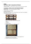
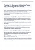
Acombinationalcircuitconsistsofinputvariables,logicgates,andoutputvaria
bles. The logic gates accept signals from inputs and output signals are
generatedaccording to the logic circuits employed in it. Binary information
from the given datatransforms to desired output data in this process. Both input
and output are obviouslythe binary signals, i.e., both the input and output
signals are of two possible states, logic1andlogic0.
Blockdiagramofacombinationallogiccircuit
Downloaded from EnggTree.com
, EnggTree.com
Fornnumberofinputvariablestoacombinationalcircuit,2npossiblecombinat
ionsofbinaryinputstatesarepossible.Foreachpossiblecombination,thereisone and
only one possible output combination. A combinational logic circuit can
bedescribed by m Boolean functions and each output can be expressed in terms
of n inputvariables.
Downloaded from EnggTree.com
, EnggTree.com
DESIGNPROCEDURE:
Anycombinationalcircuitcanbedesignedbythefollowingstepsofdesignprocedure.
1. Theproblemisstated.
2. Identifytheinputandoutputvariables.
3. Theinputandoutputvariablesareassignedlettersymbols.
4. Constructionofatruthtabletomeetinput-outputrequirements.
5. WritingBooleanexpressionsforvariousoutputvariablesintermsofinp
utvariables.
6. ThesimplifiedBooleanexpressionisobtainedbyanymethodofminimization
—algebraic method,Karnaughmapmethod,ortabulationmethod.
7. Alogicdiagramisrealizedfromthesimplifiedbooleanexpressionusinglog
icgates.
Thefollowingguidelinesshouldbefollowedwhilechoosingthepreferredformforhard
wareimplementation:
1. Theimplementationshouldhavetheminimumnumberofgates,withthegate
susedhavingtheminimumnumberofinputs.
2. Thereshouldbeaminimumnumberofinterconnections.
3. Limitationonthedrivingcapabilityofthegatesshouldnotbeignored.
ARITHMETICCIRCUITS–BASICBUILDINGBLOCKS:
Inthissection,wewilldiscussthosecombinationallogicbuildingblocksthatca
nbe used to perform addition and subtraction operations on binary numbers.
Additionand subtraction are the two most commonly used arithmetic
operations, as the othertwo, namely multiplication and division, are
respectively the processes of repeatedadditionandrepeated subtraction.
Thebasicbuildingblocksthatformthebasisofallhardwareusedtoperformthea
rithmeticoperationsonbinarynumbersarehalf-adder,fulladder,half-
subtractor,full-subtractor.
Half-Adder:
A half-adder is a combinational circuit that can be used to add two
binary bits. Ithas two inputs that represent the two bits to be added and two
outputs, with oneproducingtheSUMoutputandtheotherproducingtheCARRY.
Downloaded from EnggTree.com
CS3351-DIGITAL PRINCIPLES AND COMPUTER
ORGANIZATION
UNITICOMBINATIONALCIRCUITS:
-Combinational Circuits
– Karnaugh Map - Analysis and Design Procedures
– Binary Adder – Subtractor
– Decimal Adder
- Magnitude Comparator
– Decoder
– Encoder
– Multiplexers
- Demultiplexers
Downloaded from EnggTree.com
, EnggTree.com
INTRODUCTION:
Thedigitalsystemconsistsoftwotypesofcircuits,namely
(i) Combinationalcircuits
(ii) Sequentialcircuits
Combinationalcircuitconsistsoflogicgateswhoseoutputatanytimeisdeter
mined from the present combination of inputs. The logic gate is the most
basicbuildingblockofcombinationallogic.Thelogicalfunctionperformedbyacomb
inationalcircuitisfullydefinedbyasetofBooleanexpressions.
Sequential logic circuit comprises both logic gates and the state of
storageelementssuchasflip-
flops.Asaconsequence,theoutputofasequentialcircuitdependsnotonlyonpresentv
alueofinputs butalsoonthepaststateofinputs.
Inthepreviouschapter,wehavediscussedbinarynumbers,codes,Booleanalge
braandsimplificationofBooleanfunctionandlogicgates.Inthischapter,formulation
andanalysisofvarioussystematicdesignsofcombinationalcircuitswillbediscussed.
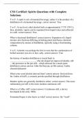
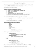
Acombinationalcircuitconsistsofinputvariables,logicgates,andoutputvaria
bles. The logic gates accept signals from inputs and output signals are
generatedaccording to the logic circuits employed in it. Binary information
from the given datatransforms to desired output data in this process. Both input
and output are obviouslythe binary signals, i.e., both the input and output
signals are of two possible states, logic1andlogic0.
Blockdiagramofacombinationallogiccircuit
Downloaded from EnggTree.com
, EnggTree.com
Fornnumberofinputvariablestoacombinationalcircuit,2npossiblecombinat
ionsofbinaryinputstatesarepossible.Foreachpossiblecombination,thereisone and
only one possible output combination. A combinational logic circuit can
bedescribed by m Boolean functions and each output can be expressed in terms
of n inputvariables.
Downloaded from EnggTree.com
, EnggTree.com
DESIGNPROCEDURE:
Anycombinationalcircuitcanbedesignedbythefollowingstepsofdesignprocedure.
1. Theproblemisstated.
2. Identifytheinputandoutputvariables.
3. Theinputandoutputvariablesareassignedlettersymbols.
4. Constructionofatruthtabletomeetinput-outputrequirements.
5. WritingBooleanexpressionsforvariousoutputvariablesintermsofinp
utvariables.
6. ThesimplifiedBooleanexpressionisobtainedbyanymethodofminimization
—algebraic method,Karnaughmapmethod,ortabulationmethod.
7. Alogicdiagramisrealizedfromthesimplifiedbooleanexpressionusinglog
icgates.
Thefollowingguidelinesshouldbefollowedwhilechoosingthepreferredformforhard
wareimplementation:
1. Theimplementationshouldhavetheminimumnumberofgates,withthegate
susedhavingtheminimumnumberofinputs.
2. Thereshouldbeaminimumnumberofinterconnections.
3. Limitationonthedrivingcapabilityofthegatesshouldnotbeignored.
ARITHMETICCIRCUITS–BASICBUILDINGBLOCKS:
Inthissection,wewilldiscussthosecombinationallogicbuildingblocksthatca
nbe used to perform addition and subtraction operations on binary numbers.
Additionand subtraction are the two most commonly used arithmetic
operations, as the othertwo, namely multiplication and division, are
respectively the processes of repeatedadditionandrepeated subtraction.
Thebasicbuildingblocksthatformthebasisofallhardwareusedtoperformthea
rithmeticoperationsonbinarynumbersarehalf-adder,fulladder,half-
subtractor,full-subtractor.
Half-Adder:
A half-adder is a combinational circuit that can be used to add two
binary bits. Ithas two inputs that represent the two bits to be added and two
outputs, with oneproducingtheSUMoutputandtheotherproducingtheCARRY.
Downloaded from EnggTree.com