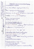
Principles of Flight & Aerodynamics
References: PHAK Chapter 4 – Principles of Flight & PHAK Chapter 5 – Aerodynamics, Bold Method Articles
Introduction: Having an understanding of basic aerodynamics and the principles of flight makes for a better pilot.
Overview
• Forces Acting on the Aircraft • Axes of an Aircraft
• Theories in the Production of Lift • Airplane Stability and Controllability
• Airfoil Design • Left Turning Tendencies
• Wing Planform • Load Factors
• Wingtip Vortices • Appendix – Additional Topics
• Ground Effect
*Review Flight control and axis of flight if not previously reviewed
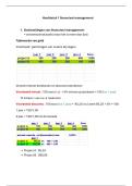
Forces Acting on the Aircraft - Lift, Weight, Thrust, & Drag
See PHAK Chapter 5 page 2, See Bold Method CFI Tool – Forces in a Climb or Descent
*Draw plane with 4 forces
Lift
• Upward force produced by the effect of the air acting on the airfoil
• In level flight, lift opposes downward force of weight
• Acts perpendicular to the flight path through the center of lift (CL)
• Pilots utilize AOA and airspeed (velocity) to adjust lift
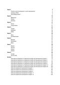
Airfoil Design Characteristics – Intro
*Draw and label airfoil or show image
• An airfoil is a structure designed to obtain a useful reaction (e.g. lift) from air moving over its surface.
• Many different design characteristics of an airfoil, which can be altered to create different shapes/profiles (see PHAK Ch.4
pg. 7). Airfoil design is dependent upon the purpose of the aircraft.
Some airfoil terms you should be familiar with include: (see PHAK Ch. 4 pg.7)
Camber – difference in the curvatures of the upper and lower surfaces of the airfoil
Leading Edge
Trailing Edge
Chord line – reference line; straight line drawn through the profile connecting the leading and trailing edge
Mean camber line – reference line; drawn from the leading edge to the trailing edge, while remaining equidistant from the
upper and lower surfaces
Angle of Attack (AOA) – the angle between the chord line of the airfoil and the direction of the relative wind (PHAK 4 pg.8)
Angle of Incidence – the angle between the chord line of the airfoil and the longitudinal axis of the aircraft
1
, Theories in the Production of Lift
Lift is based on several important principles: 1) Newton’s Third Law 2) Bernoulli’s Principle of Differential Pressure
Newton’s Third Law: “For every action, there is an equal and opposite reaction.”
Aircraft Wing:
1. As air strikes the lower surface of the wing when inclined at a small angle to its direction of motion, the air is forced to
rebound downward, causing an upward reaction in lift.
2. The downward backward flow from the top surface of an airfoil creates a downwash. The reaction of this downwash results
in an upward forward force on the airfoil.
Propeller: The propeller moves and pushes back the air; consequently, the air pushes the propeller and thus the airplane in the
opposite direction - forward
Bernoulli’s Principle of Differential Pressure: As the velocity of a fluid increases, the pressure within the fluid decreases.
Aircraft Wing: As the wing moves through the air, the flow of air across the curved top surface increases in velocity creating a
low-pressure area above the wing
Propeller: Propellers accelerate airflow over their cambered surfaces – the high velocity of the air results in lower static
pressure in front of the propeller, pulling the airfoil forward
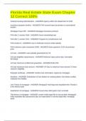
Angle of Attack
• Any time the control yoke or stick is moved fore or aft, the AOA is changed
• As AOA increases, lift increases (all other factors being equal)
o When the aircraft reaches the maximum AOA, lift begins to diminish rapidly - This is the stalling AOA, known as
critical AOA (CL-MAX) (see PHAK Chapter 5 page 4)
Airspeed (Velocity)
• If an aircraft is to keep flying the lift-producing airfoil must keep moving
o This is accomplished by the forward speed of the aircraft’s velocity
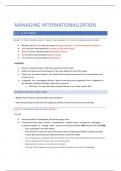
Lift Equation
CL = coefficient of lift
Ρ = air density
V = airfoil velocity
S = surface area of wing
Controlling Aerodynamic Factors in Lift Equation
• Two major aerodynamic factors from the pilot’s viewpoint are lift and airspeed
o These can be controlled readily and accurately
• Pilot can control density by adjusting altitude
• Pilot can control wing area if the aircraft happens to have flaps that enlarge wing area
• Surface area can also be altered by the camber, planform, aspect ratio, and wing area are some design factors that can
impacts a wing’s lift capabilities.
Weight
• Weight is the force of gravity pulling the aircraft down to the center of the earth
• In straight and level flight, lift = weight
• If lift becomes less than weight, the aircraft will descend
• If lift becomes greater than weight, the aircraft will climb
• Combined load of the aircraft, crew, fuel, cargo, baggage – not constant (e.g., changes with fuel burning during flight)
• Weight is not constant and will change due to what is loaded onto the plane and fuel burning throughout the flight
• Always extends and pivots from the Center of gravity (CG)
2
, Thrust
• Forward force produced by the powerplant/propeller/ or rotor
• Opposes or overcomes the force of drag
• In general, it acts parallel to the longitudinal axis but this is not always the case
• The pilot uses a combination of thrust and AOA to hold the aircraft in level flight
• If thrust decreases, airspeed decreases and lift will become less than weight
o The aircraft will start to descend unless AOA is increased
• If thrust is increased, the aircraft speeds up and lift increases
o The aircraft will start to climb unless AOA is decreased
Drag
• See Bold Method Article – Types of Drag, PHAK Chapter 5 page 6-8
• Rearward force caused by disruption of airflow by the wing, fuselage, and other protruding objects
• Opposes thrust
• Acts rearward parallel to the relative wind
Parasite drag: 1. Form drag Generated by the aircraft due to its shape and airflow around it
functions in no o Compare the cross section of a Cherokee/C172 to a Lancair or an F16
way to aid in 2. Interference Comes from the intersection of airstreams that creates:
flight. 3 types. drag o Eddy currents
Faster airspeed o Turbulence
increased o Restricts smooth airflow
parasite drag. Examples: Wing struts & Intersection of the wing and the fuselage at the wing root
Greatest when two surfaces meet at perpendicular angles
o Fairings are used to reduce interference drag
3. Skin friction • Every surface, no matter how smooth, has a rough, ragged surface when viewed under
drag high magnification
• Air molecules come into contact with the surface of the wing, stopping movement
• Each layer of molecules above the surface moves slightly faster until the molecules are
moving at the velocity of the air moving around the aircraft - This speed is called free-
stream velocity.
• The area between the wing and the free-stream velocity is about as thick as a playing
card and is called the boundary layer
Skin Friction Reduction
• Designers utilize flush mount rivets and remove any irregularities that may protrude
above the wing surface
• Smooth and glossy finish aids in transition of air across the surface of the wing - New
paint jobs provide smoother surface & keeping AC cleaned and waxed helps
Induced drag: • Induced drag is inherent whenever an airfoil is producing lift
result of • As AOA increases, induced drag increases
producing lift o The lower the airspeed, the greater the induced drag (due to larger pressure differential)
Downwash (from Wingtip Vortices)
• Induced downwash from wing tip vortices behind the wing’s trailing edge causes induced drag
• Downwash points the relative wind downward – the more downwash, the more the relative wind points
downward - This is important as lift is always perpendicular to the relative wind
• The more downwash, the more your lift vector points backwards, creating a rearward component of lift
– this is induced drag
3
References: PHAK Chapter 4 – Principles of Flight & PHAK Chapter 5 – Aerodynamics, Bold Method Articles
Introduction: Having an understanding of basic aerodynamics and the principles of flight makes for a better pilot.
Overview
• Forces Acting on the Aircraft • Axes of an Aircraft
• Theories in the Production of Lift • Airplane Stability and Controllability
• Airfoil Design • Left Turning Tendencies
• Wing Planform • Load Factors
• Wingtip Vortices • Appendix – Additional Topics
• Ground Effect
*Review Flight control and axis of flight if not previously reviewed
Forces Acting on the Aircraft - Lift, Weight, Thrust, & Drag
See PHAK Chapter 5 page 2, See Bold Method CFI Tool – Forces in a Climb or Descent
*Draw plane with 4 forces
Lift
• Upward force produced by the effect of the air acting on the airfoil
• In level flight, lift opposes downward force of weight
• Acts perpendicular to the flight path through the center of lift (CL)
• Pilots utilize AOA and airspeed (velocity) to adjust lift
Airfoil Design Characteristics – Intro
*Draw and label airfoil or show image
• An airfoil is a structure designed to obtain a useful reaction (e.g. lift) from air moving over its surface.
• Many different design characteristics of an airfoil, which can be altered to create different shapes/profiles (see PHAK Ch.4
pg. 7). Airfoil design is dependent upon the purpose of the aircraft.
Some airfoil terms you should be familiar with include: (see PHAK Ch. 4 pg.7)
Camber – difference in the curvatures of the upper and lower surfaces of the airfoil
Leading Edge
Trailing Edge
Chord line – reference line; straight line drawn through the profile connecting the leading and trailing edge
Mean camber line – reference line; drawn from the leading edge to the trailing edge, while remaining equidistant from the
upper and lower surfaces
Angle of Attack (AOA) – the angle between the chord line of the airfoil and the direction of the relative wind (PHAK 4 pg.8)
Angle of Incidence – the angle between the chord line of the airfoil and the longitudinal axis of the aircraft
1
, Theories in the Production of Lift
Lift is based on several important principles: 1) Newton’s Third Law 2) Bernoulli’s Principle of Differential Pressure
Newton’s Third Law: “For every action, there is an equal and opposite reaction.”
Aircraft Wing:
1. As air strikes the lower surface of the wing when inclined at a small angle to its direction of motion, the air is forced to
rebound downward, causing an upward reaction in lift.
2. The downward backward flow from the top surface of an airfoil creates a downwash. The reaction of this downwash results
in an upward forward force on the airfoil.
Propeller: The propeller moves and pushes back the air; consequently, the air pushes the propeller and thus the airplane in the
opposite direction - forward
Bernoulli’s Principle of Differential Pressure: As the velocity of a fluid increases, the pressure within the fluid decreases.
Aircraft Wing: As the wing moves through the air, the flow of air across the curved top surface increases in velocity creating a
low-pressure area above the wing
Propeller: Propellers accelerate airflow over their cambered surfaces – the high velocity of the air results in lower static
pressure in front of the propeller, pulling the airfoil forward
Angle of Attack
• Any time the control yoke or stick is moved fore or aft, the AOA is changed
• As AOA increases, lift increases (all other factors being equal)
o When the aircraft reaches the maximum AOA, lift begins to diminish rapidly - This is the stalling AOA, known as
critical AOA (CL-MAX) (see PHAK Chapter 5 page 4)
Airspeed (Velocity)
• If an aircraft is to keep flying the lift-producing airfoil must keep moving
o This is accomplished by the forward speed of the aircraft’s velocity
Lift Equation
CL = coefficient of lift
Ρ = air density
V = airfoil velocity
S = surface area of wing
Controlling Aerodynamic Factors in Lift Equation
• Two major aerodynamic factors from the pilot’s viewpoint are lift and airspeed
o These can be controlled readily and accurately
• Pilot can control density by adjusting altitude
• Pilot can control wing area if the aircraft happens to have flaps that enlarge wing area
• Surface area can also be altered by the camber, planform, aspect ratio, and wing area are some design factors that can
impacts a wing’s lift capabilities.
Weight
• Weight is the force of gravity pulling the aircraft down to the center of the earth
• In straight and level flight, lift = weight
• If lift becomes less than weight, the aircraft will descend
• If lift becomes greater than weight, the aircraft will climb
• Combined load of the aircraft, crew, fuel, cargo, baggage – not constant (e.g., changes with fuel burning during flight)
• Weight is not constant and will change due to what is loaded onto the plane and fuel burning throughout the flight
• Always extends and pivots from the Center of gravity (CG)
2
, Thrust
• Forward force produced by the powerplant/propeller/ or rotor
• Opposes or overcomes the force of drag
• In general, it acts parallel to the longitudinal axis but this is not always the case
• The pilot uses a combination of thrust and AOA to hold the aircraft in level flight
• If thrust decreases, airspeed decreases and lift will become less than weight
o The aircraft will start to descend unless AOA is increased
• If thrust is increased, the aircraft speeds up and lift increases
o The aircraft will start to climb unless AOA is decreased
Drag
• See Bold Method Article – Types of Drag, PHAK Chapter 5 page 6-8
• Rearward force caused by disruption of airflow by the wing, fuselage, and other protruding objects
• Opposes thrust
• Acts rearward parallel to the relative wind
Parasite drag: 1. Form drag Generated by the aircraft due to its shape and airflow around it
functions in no o Compare the cross section of a Cherokee/C172 to a Lancair or an F16
way to aid in 2. Interference Comes from the intersection of airstreams that creates:
flight. 3 types. drag o Eddy currents
Faster airspeed o Turbulence
increased o Restricts smooth airflow
parasite drag. Examples: Wing struts & Intersection of the wing and the fuselage at the wing root
Greatest when two surfaces meet at perpendicular angles
o Fairings are used to reduce interference drag
3. Skin friction • Every surface, no matter how smooth, has a rough, ragged surface when viewed under
drag high magnification
• Air molecules come into contact with the surface of the wing, stopping movement
• Each layer of molecules above the surface moves slightly faster until the molecules are
moving at the velocity of the air moving around the aircraft - This speed is called free-
stream velocity.
• The area between the wing and the free-stream velocity is about as thick as a playing
card and is called the boundary layer
Skin Friction Reduction
• Designers utilize flush mount rivets and remove any irregularities that may protrude
above the wing surface
• Smooth and glossy finish aids in transition of air across the surface of the wing - New
paint jobs provide smoother surface & keeping AC cleaned and waxed helps
Induced drag: • Induced drag is inherent whenever an airfoil is producing lift
result of • As AOA increases, induced drag increases
producing lift o The lower the airspeed, the greater the induced drag (due to larger pressure differential)
Downwash (from Wingtip Vortices)
• Induced downwash from wing tip vortices behind the wing’s trailing edge causes induced drag
• Downwash points the relative wind downward – the more downwash, the more the relative wind points
downward - This is important as lift is always perpendicular to the relative wind
• The more downwash, the more your lift vector points backwards, creating a rearward component of lift
– this is induced drag
3