STUDY GUIDE
Introduction to Networking - Foundation of Switching Operations
Objectives
This module covers the following objectives in learning the concepts about the foundation of switching
operations, configuring network switches, and troubleshooting networking scenarios:
➢ Explain the basic switching concepts and the operations.
➢ Perform and verify initial switch configuration tasks including remote access management.
➢ Verify network status and switch operation using basic utilities (including: ping, traceroute, telnet, SSH,
ARP, ipconfig), SHOW and DEBUG commands.
Study Strategies
➢ Read and patiently understand the discussion presented in this module.
➢ Smartly rewrite in your notebook or make a summary of notes about the information being presented. By
this strategy, you will learn how to visualize the concepts and imagine how a switch fundamentally
operates in a network environment.
➢ Complete the challenge and the exercises at the end of the module. This will solidify the concepts that
you have learned through simulation. Simulation will be done by group and you need to collaborate with
your group members.
Introduction
In our previous face-to-face classes, we have already discussed the two (2) important models used in
establishing a network – The OSI Model and the TCIP/IP Model. Through these models, we have learned that in
order for all networking devices, regardless of who the vendor is, to communicate, they all need a standard way
of communication. Furthermore, through these models, we have learned that for every layer, there is a specific
device that operates based on the concept of operation on that layer. Layer 1 is for cabling and passive devices,
Layer 2 is for bridges and switches, and Layer 3 is for routers and layer 3 switches.
In this new normal type of lesson, we will be focusing more on the in-depth discussion of layer 2 device
operations – fundamentals of switching operation. Alright! Let’s do this! *insert Sir Tim’s voice and energy hehe*
Understanding Switch Topology
The network infrastructure of an organization really depends on the size of it – the bigger the company,
the larger the network and the smaller the company, the smaller the network is. And because of this difference in
scale, relies also how the network engineers will setup their devices on their network infrastructure. This includes
all the conditions and constraints of their company when it comes to their day to day operation and most
infrastructure follows the recommendation of Cisco – the Cisco Hierarchical Design.
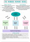
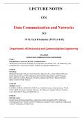
As you can see in the ideal network design, switches are used on all layers but, in practical network design,
switches are most used in the Distribution (Layer 3 switches) and Access (Layer 2 switches) layers. By design,
distribution switches carry traffic from the access layer going up to the core layer of the infrastructure and vice
versa – it distributes incoming and outgoing traffic. On the other hand, access layer switches are used to group
and connect all the end devices to the network frame itself.
JCQ.ECE 1
, Illustration 1. The Cisco Hierarchical Design
Layer 2 and Layer 3 Switches
One key difference of these two (2) types of switches is just that layer 3 switches are capable of processing
layer 3 protocols or simply known as routing. It means that these layer 3 switches have the capability to move
packets using routing processes such as EIGRP (Enhanced Interior Gateway Protocol) and OSPF (Open
Shortest Path First). They can route the packets from its source to destination at wire speed. This is also the
reason why these switches are implemented in distribution layer.
Layer 2 switches use only MAC address to move frames within the network while layer 3 switches use
MAC address and/or IP address to move frames or packets within a network.
Basic Switch Functionality
Let us refer to the illustration below (Illustration 2). Supposed that PC_1 and SERVER_1 are connected
initially via SW_1 and PC_1 wants to send a ping request to SERVER_1. Remember that switches forward frames
based on the Layer 2 Ethernet MAC addresses. These devices receive Ethernet frames transmitted from other
devices and dynamically build a MAC address table based on the source MAC address inside those frames. This
MAC address table is commonly referred to as a Content Addressable Memory (CAM) table.
At the initial instance that the two devices were connected, the switch has no idea on what ports these two
devices are plugged in. As the ping request of the PC_1 is sent through the switch, the switch will recognize the
frame coming from PC_1 via Fa 0/1 through its source MAC address tagged on its ethernet frame and going to a
JCQ.ECE 2
Introduction to Networking - Foundation of Switching Operations
Objectives
This module covers the following objectives in learning the concepts about the foundation of switching
operations, configuring network switches, and troubleshooting networking scenarios:
➢ Explain the basic switching concepts and the operations.
➢ Perform and verify initial switch configuration tasks including remote access management.
➢ Verify network status and switch operation using basic utilities (including: ping, traceroute, telnet, SSH,
ARP, ipconfig), SHOW and DEBUG commands.
Study Strategies
➢ Read and patiently understand the discussion presented in this module.
➢ Smartly rewrite in your notebook or make a summary of notes about the information being presented. By
this strategy, you will learn how to visualize the concepts and imagine how a switch fundamentally
operates in a network environment.
➢ Complete the challenge and the exercises at the end of the module. This will solidify the concepts that
you have learned through simulation. Simulation will be done by group and you need to collaborate with
your group members.
Introduction
In our previous face-to-face classes, we have already discussed the two (2) important models used in
establishing a network – The OSI Model and the TCIP/IP Model. Through these models, we have learned that in
order for all networking devices, regardless of who the vendor is, to communicate, they all need a standard way
of communication. Furthermore, through these models, we have learned that for every layer, there is a specific
device that operates based on the concept of operation on that layer. Layer 1 is for cabling and passive devices,
Layer 2 is for bridges and switches, and Layer 3 is for routers and layer 3 switches.
In this new normal type of lesson, we will be focusing more on the in-depth discussion of layer 2 device
operations – fundamentals of switching operation. Alright! Let’s do this! *insert Sir Tim’s voice and energy hehe*
Understanding Switch Topology
The network infrastructure of an organization really depends on the size of it – the bigger the company,
the larger the network and the smaller the company, the smaller the network is. And because of this difference in
scale, relies also how the network engineers will setup their devices on their network infrastructure. This includes
all the conditions and constraints of their company when it comes to their day to day operation and most
infrastructure follows the recommendation of Cisco – the Cisco Hierarchical Design.
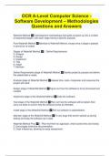
As you can see in the ideal network design, switches are used on all layers but, in practical network design,
switches are most used in the Distribution (Layer 3 switches) and Access (Layer 2 switches) layers. By design,
distribution switches carry traffic from the access layer going up to the core layer of the infrastructure and vice
versa – it distributes incoming and outgoing traffic. On the other hand, access layer switches are used to group
and connect all the end devices to the network frame itself.
JCQ.ECE 1
, Illustration 1. The Cisco Hierarchical Design
Layer 2 and Layer 3 Switches
One key difference of these two (2) types of switches is just that layer 3 switches are capable of processing
layer 3 protocols or simply known as routing. It means that these layer 3 switches have the capability to move
packets using routing processes such as EIGRP (Enhanced Interior Gateway Protocol) and OSPF (Open
Shortest Path First). They can route the packets from its source to destination at wire speed. This is also the
reason why these switches are implemented in distribution layer.
Layer 2 switches use only MAC address to move frames within the network while layer 3 switches use
MAC address and/or IP address to move frames or packets within a network.
Basic Switch Functionality
Let us refer to the illustration below (Illustration 2). Supposed that PC_1 and SERVER_1 are connected
initially via SW_1 and PC_1 wants to send a ping request to SERVER_1. Remember that switches forward frames
based on the Layer 2 Ethernet MAC addresses. These devices receive Ethernet frames transmitted from other
devices and dynamically build a MAC address table based on the source MAC address inside those frames. This
MAC address table is commonly referred to as a Content Addressable Memory (CAM) table.
At the initial instance that the two devices were connected, the switch has no idea on what ports these two
devices are plugged in. As the ping request of the PC_1 is sent through the switch, the switch will recognize the
frame coming from PC_1 via Fa 0/1 through its source MAC address tagged on its ethernet frame and going to a
JCQ.ECE 2