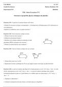
Assume you are given an unknown first-order RC two port network but are able to measure the
magnitude and phase plots of its transfer function as shown in below: What common filter
characteristic corresponds to these graphs? Draw the Bode plot for the unknown network and
mark the break frequency and slope. What Is the transfer function of the RC circuit which leads
to this response? Give the value for the break frequency and use a transfer function which is
expressed in terms of this frequency. Draw the RC circuit diagram and label the input voltage
source v1 and output v0. Assuming a 1 mu F capacitor is used in the circuit, what would be the
correct value of the resistor to achieve this break frequency?
Solution
1. The graphs corresponds to a HIGH PASS FILTER, that allows signals of frequency greater
than the break frequency.
Break, frequency is the frequency at which phase difference is 45o or magnitude ot the transfer
function is max/2
Form the curves given, the break frequency fB ˜ 40Hz
ii) The circuit has a resistor R in sereis with the capacitor, the input signal is applied across them
and the output is taken across the resistor.
Let Vi be the input signal
Let Vo be the output signal
The impedance of the circuit Z = R - jXC
The current in the circuit I = Vin / Z
The output voltage is the voltage across the resistor
Vo = IR
Vo = VinR/Z
Vo = Vin R / (R-jXC)
Transfer function
Vo / Vin = R / (R-jXC)
Vo / Vin = 1 / (1-jXC /R)
Vo / Vin = 1 / (1-j1/CR)
Vo / Vin = 1 / (1-jB /)
or
Vo / Vin = 1 / (1-jfB /f)