CSN205 Static Networks
Lab 1 Switch Management in a Small Ethernet LAN
Student First Name: Student Last Name:
Student Number: Submission Date:
Notes
1. Type your name, student ID, and the submission date in the fields above.
2. Follow the procedure of the lab and fulfill all requirements.
3. Answer all questions in the provided spaces (preferably in the red-bold font).
4. Submit this document and the packet tracer file in Blackboard by the due date.
5. The mark and possible feedback will be posted in Blackboard after the due date.
Objectives
1. To gain skills for achieving basic management of a switch.
2. To configure the IP addresses of host computers.
3. To check the status of the interfaces of a switch.
4. To examine the MAC address table entries of a switch before and after running the ARP process.
5. To achieve a basic configuration of a switch.
6. To add security for accessing the configuration of a switch.
7. To enable remote access of a switch configuration within a simple Ethernet LAN.
Network Topology
DCN286 Introduction to Data Communications, School of ITAS, Seneca College Page 1
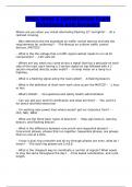
, Figure 1 Topology of the Ethernet LAN network.
In packet tracer construct the Ethernet LAN network shown in Figure 1. Use the Cisco 2960 module
for each of switches SW1 and SW2. Use copper straight-through cables to connect Fa0 of PC1 to
Fa0/1 of SW1, Fa0 of PC2 to Fa0/2 of SW1, Fa0 of PC3 to Fa0/1 of SW2, and Fa0 of PC4 to Fa0/2 of
SW2. Note that Fa0 here refers to the FastEthernet port of the NIC of the PC, and Fa0/n (where n is
an integer number) is one of the FastEthernet ports of the switch. Also, connect the Fa0/3 ports of
SW1 and SW2 using a copper cross-over cable. To console from PC1 to SW1 connect a console
cable from the RS232 connector of PC1 to the Console port of SW1. Also to console from PC3 to
SW2 connect a console cable from the RS232 connector of PC3 to the Console port of SW2. Notice
that the IP address of the NIC of each PC is indicated in the figure. Also, the IP addresses of the
administrative VLAN 1 of SW1 and SW2 are indicated in the figure.
Procedure
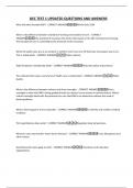
1. Click on PC1 and in the Desktop tab open the IP Configuration application. Enter the IP address
10.0.0.1 of PC1 and notice that the mask will be set to 255.0.0.0. Notice that you can change the
Display Name of the PC in the Config tab. See Figure 2 for the configuration of the IP address of
PC1. Repeat the same procedure to configure the IP addresses of each of PC2, PC3, and PC4.
Figure 2 Configuring the IP address of PC1.
In Figure 3 below insert an image for the configuration of the IP address of PC4.
DCN286 Introduction to Data Communications, School of ITAS, Seneca College Page 2
Lab 1 Switch Management in a Small Ethernet LAN
Student First Name: Student Last Name:
Student Number: Submission Date:
Notes
1. Type your name, student ID, and the submission date in the fields above.
2. Follow the procedure of the lab and fulfill all requirements.
3. Answer all questions in the provided spaces (preferably in the red-bold font).
4. Submit this document and the packet tracer file in Blackboard by the due date.
5. The mark and possible feedback will be posted in Blackboard after the due date.
Objectives
1. To gain skills for achieving basic management of a switch.
2. To configure the IP addresses of host computers.
3. To check the status of the interfaces of a switch.
4. To examine the MAC address table entries of a switch before and after running the ARP process.
5. To achieve a basic configuration of a switch.
6. To add security for accessing the configuration of a switch.
7. To enable remote access of a switch configuration within a simple Ethernet LAN.
Network Topology
DCN286 Introduction to Data Communications, School of ITAS, Seneca College Page 1
, Figure 1 Topology of the Ethernet LAN network.
In packet tracer construct the Ethernet LAN network shown in Figure 1. Use the Cisco 2960 module
for each of switches SW1 and SW2. Use copper straight-through cables to connect Fa0 of PC1 to
Fa0/1 of SW1, Fa0 of PC2 to Fa0/2 of SW1, Fa0 of PC3 to Fa0/1 of SW2, and Fa0 of PC4 to Fa0/2 of
SW2. Note that Fa0 here refers to the FastEthernet port of the NIC of the PC, and Fa0/n (where n is
an integer number) is one of the FastEthernet ports of the switch. Also, connect the Fa0/3 ports of
SW1 and SW2 using a copper cross-over cable. To console from PC1 to SW1 connect a console
cable from the RS232 connector of PC1 to the Console port of SW1. Also to console from PC3 to
SW2 connect a console cable from the RS232 connector of PC3 to the Console port of SW2. Notice
that the IP address of the NIC of each PC is indicated in the figure. Also, the IP addresses of the
administrative VLAN 1 of SW1 and SW2 are indicated in the figure.
Procedure
1. Click on PC1 and in the Desktop tab open the IP Configuration application. Enter the IP address
10.0.0.1 of PC1 and notice that the mask will be set to 255.0.0.0. Notice that you can change the
Display Name of the PC in the Config tab. See Figure 2 for the configuration of the IP address of
PC1. Repeat the same procedure to configure the IP addresses of each of PC2, PC3, and PC4.
Figure 2 Configuring the IP address of PC1.
In Figure 3 below insert an image for the configuration of the IP address of PC4.
DCN286 Introduction to Data Communications, School of ITAS, Seneca College Page 2