6 – Input - Output
Write a short note on Device Controller. OR
(1) Explain Device Controller in brief.
• I/O unit consist of a mechanical component and an electronic component. Electronic
component of I/O devices is called the Device Controller.
• The mechanical component is device itself.
• The controller card usually has a connector on it, into which a cable leading to the
device itself can be plugged.
• Some devices have their own built in controller. Many controllers have two, four or
even eight identical devices.
• If the interface between the controller and device is a standard interfacing (ISO, ANSI
or IEEE), then companies can make device or controller that fit that interface.
• The controllers are used to convert the serial bit stream into a block of bytes and
perform any error correction if necessary.
• The block of bytes is typically first assembled bit by bit in buffer inside controller.
• After verification, the block has been declared to be error free, and then it can be
copied to main memory.
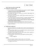
(2) Explain Memory-Mapped I/O
• Each device controller has a few registers that are used for communicating with the
CPU.
• By writing into these registers, the OS can command the device to deliver data, accept
data, switch itself on or off, or perform some action.
• By reading from these registers OS can learn what the device’s status is, whether it is
prepared to accept a new command and so on.
• There are two ways to communicate with control registers and the device buffers
▪ I/O Port.
▪ Memory mapped I/O.
I/O Port
• Each control register is assigned an I/O port number, an 8 or 16 bit integer.
• The set of all the I/O ports form the I/O port space and is protected so that ordinary
user program cannot access it.
1
, 6 – Input - Output
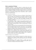
Memory-Mapped I/O
• Memory mapped I/O is an approach to map all the control registers into memory
space.
• Each control register is assigned a unique memory address to which no memory is
assigned, this system is called memory mapped I/O.
• Generally assigned addresses are at the top of the address space.
• When CPU wants to read a word, either from memory or an I/O port, it puts the
address it needs on the bus’ address lines and then issues a READ signal on bus’ control
line.
• A second signal line is used to tell whether I/O space or memory space is needed.
• If it is memory space, the memory responds to the request. If it is I/O space, the I/O
device responds to the request.
Figure 6-1. (a) Separate I/O and memory space. (b) Memory-mapped I/O. (c) Hybrid.
• Advantages:
▪ With memory mapped I/O, device control registers are just variables in
memory. So with memory mapped I/O device drivers can easily be written in ‘C’
like languages, no assembly code is required to access registers.
▪ No special protection mechanism is needed to keep user processes from
performing I/O.
▪ With memory-mapped I/O, every instruction that can reference memory can
also reference control registers.
• Disadvantages:
▪ Most computers nowadays have some form of cashing of memory words.
Cashing a device control registers would create problems, cashing needs to be
2
, 6 – Input - Output
disabled in paging system.
▪ If there is only one address space, then all memory modules and all I/O devices
must examine all memory reference to see which ones to respond to.
(3) Explain the Direct Memory Access.
• CPU needs to address the device controllers to exchange data with them.
• CPU can request data from an I/O controller one byte at a time, which is wastage of
time.
• So a different scheme called DMA (Direct Memory Access) is used. The operating
system can only use DMA if the hardware has DMA controller.
• A DMA controller is available for regulating transfers to multiple devices.
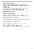
• The DMA controller has separate access to the system bus independent to CPU as
shown in figure 6-2. It contains several registers that can be written and read by CPU.
• These registers includes memory address register, a byte count register, one or more
control registers.
Figure 6-2. Operation of a DMA transfer
Disk read-write without a DMA
• The disk controller reads the block from the drive serially, bit by bit, until the entire
block is in the controller’s buffer.
• Next, it computes the checksum to verify that no read errors have occurred.
3
Write a short note on Device Controller. OR
(1) Explain Device Controller in brief.
• I/O unit consist of a mechanical component and an electronic component. Electronic
component of I/O devices is called the Device Controller.
• The mechanical component is device itself.
• The controller card usually has a connector on it, into which a cable leading to the
device itself can be plugged.
• Some devices have their own built in controller. Many controllers have two, four or
even eight identical devices.
• If the interface between the controller and device is a standard interfacing (ISO, ANSI
or IEEE), then companies can make device or controller that fit that interface.
• The controllers are used to convert the serial bit stream into a block of bytes and
perform any error correction if necessary.
• The block of bytes is typically first assembled bit by bit in buffer inside controller.
• After verification, the block has been declared to be error free, and then it can be
copied to main memory.
(2) Explain Memory-Mapped I/O
• Each device controller has a few registers that are used for communicating with the
CPU.
• By writing into these registers, the OS can command the device to deliver data, accept
data, switch itself on or off, or perform some action.
• By reading from these registers OS can learn what the device’s status is, whether it is
prepared to accept a new command and so on.
• There are two ways to communicate with control registers and the device buffers
▪ I/O Port.
▪ Memory mapped I/O.
I/O Port
• Each control register is assigned an I/O port number, an 8 or 16 bit integer.
• The set of all the I/O ports form the I/O port space and is protected so that ordinary
user program cannot access it.
1
, 6 – Input - Output
Memory-Mapped I/O
• Memory mapped I/O is an approach to map all the control registers into memory
space.
• Each control register is assigned a unique memory address to which no memory is
assigned, this system is called memory mapped I/O.
• Generally assigned addresses are at the top of the address space.
• When CPU wants to read a word, either from memory or an I/O port, it puts the
address it needs on the bus’ address lines and then issues a READ signal on bus’ control
line.
• A second signal line is used to tell whether I/O space or memory space is needed.
• If it is memory space, the memory responds to the request. If it is I/O space, the I/O
device responds to the request.
Figure 6-1. (a) Separate I/O and memory space. (b) Memory-mapped I/O. (c) Hybrid.
• Advantages:
▪ With memory mapped I/O, device control registers are just variables in
memory. So with memory mapped I/O device drivers can easily be written in ‘C’
like languages, no assembly code is required to access registers.
▪ No special protection mechanism is needed to keep user processes from
performing I/O.
▪ With memory-mapped I/O, every instruction that can reference memory can
also reference control registers.
• Disadvantages:
▪ Most computers nowadays have some form of cashing of memory words.
Cashing a device control registers would create problems, cashing needs to be
2
, 6 – Input - Output
disabled in paging system.
▪ If there is only one address space, then all memory modules and all I/O devices
must examine all memory reference to see which ones to respond to.
(3) Explain the Direct Memory Access.
• CPU needs to address the device controllers to exchange data with them.
• CPU can request data from an I/O controller one byte at a time, which is wastage of
time.
• So a different scheme called DMA (Direct Memory Access) is used. The operating
system can only use DMA if the hardware has DMA controller.
• A DMA controller is available for regulating transfers to multiple devices.
• The DMA controller has separate access to the system bus independent to CPU as
shown in figure 6-2. It contains several registers that can be written and read by CPU.
• These registers includes memory address register, a byte count register, one or more
control registers.
Figure 6-2. Operation of a DMA transfer
Disk read-write without a DMA
• The disk controller reads the block from the drive serially, bit by bit, until the entire
block is in the controller’s buffer.
• Next, it computes the checksum to verify that no read errors have occurred.
3