INVESTIGATING THE DCLT BANDPASS MODEM
Abstract:
1. Aim
Understanding the Technilab DCLT, its operating
principles, digital communications, and the
techniques of digital modulation, in particular FSK
for message modulation.
2. Prerequisites
2.1. Theoretical
Type here
2.2. Software
Type here
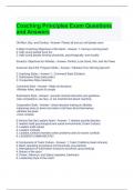
Figure 2 Circuit topology of DCLT 006
3. Materials & Methods
To observe the inputs and on the board shown, the
3.1. Hardware following further equipment was used to ensure the
This practical involved making use of the circuit was operating correctly and ready to allow
Technilab DCLT, a set of OEM printed circuit measurements to be taken:
boards containing circuit elements relating to
modulating and demodulating signals, as well as • 2x DCLT OEM boards.
creating analogue carrier signals to modulate with • Hantek 70MHz digital storage
digital messages. [1] oscilloscope
• 1x USB storage device
The board DCLT 005 contains signal generation
• 2x oscilloscope 10:1 probe leads
components for both digital and analogue
• 1x OEM Power Supply
generation, whilst DCLT 006 contained the
• Several jumper leads for connecting points
demonulating circuits for the associated modulation
on the boards
techniques. The following figures show the circuits
with terminals highlighted that were utilized in this 3.2. Circuit and Associated Theory
practical.
3.2.1. Modulation & Signal Types
In any communications system, transmitting data
across a channel generally requires the modulation
of a message signal with a higher frequency carrier
waveform. [] The result of this is a band pass
waveform. However, the modulation process is an
analogue signal, whilst digital data is modulated.
The DCLT allows an analogue carrier wave to
modulate digital data.
In this practical the focus for the digital data was on
generating a pseudo-random non-return-to-zero
(NRZ) coded digital signal as a message. In
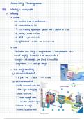
Figure 1 Circuit topology of DCLT 005 particular, NRZ-L was required. NRZ coding is
called this because it does not have a defined rest
state; that is, the signal does not return to zero with
the data clock of the system. Specifically, NRZ-L
(Level coding) allows for easy representation of a
digital logic message; “1” = logic level high and “0”
Abstract:
1. Aim
Understanding the Technilab DCLT, its operating
principles, digital communications, and the
techniques of digital modulation, in particular FSK
for message modulation.
2. Prerequisites
2.1. Theoretical
Type here
2.2. Software
Type here
Figure 2 Circuit topology of DCLT 006
3. Materials & Methods
To observe the inputs and on the board shown, the
3.1. Hardware following further equipment was used to ensure the
This practical involved making use of the circuit was operating correctly and ready to allow
Technilab DCLT, a set of OEM printed circuit measurements to be taken:
boards containing circuit elements relating to
modulating and demodulating signals, as well as • 2x DCLT OEM boards.
creating analogue carrier signals to modulate with • Hantek 70MHz digital storage
digital messages. [1] oscilloscope
• 1x USB storage device
The board DCLT 005 contains signal generation
• 2x oscilloscope 10:1 probe leads
components for both digital and analogue
• 1x OEM Power Supply
generation, whilst DCLT 006 contained the
• Several jumper leads for connecting points
demonulating circuits for the associated modulation
on the boards
techniques. The following figures show the circuits
with terminals highlighted that were utilized in this 3.2. Circuit and Associated Theory
practical.
3.2.1. Modulation & Signal Types
In any communications system, transmitting data
across a channel generally requires the modulation
of a message signal with a higher frequency carrier
waveform. [] The result of this is a band pass
waveform. However, the modulation process is an
analogue signal, whilst digital data is modulated.
The DCLT allows an analogue carrier wave to
modulate digital data.
In this practical the focus for the digital data was on
generating a pseudo-random non-return-to-zero
(NRZ) coded digital signal as a message. In
Figure 1 Circuit topology of DCLT 005 particular, NRZ-L was required. NRZ coding is
called this because it does not have a defined rest
state; that is, the signal does not return to zero with
the data clock of the system. Specifically, NRZ-L
(Level coding) allows for easy representation of a
digital logic message; “1” = logic level high and “0”