Debre Tabor University
Faculty of Technology
Department of Mechanical Engineering
Finite Element Method for Springs
By
Desu Eshatie
10-Feb-22
,Outlines
❶ Derivation of element stiffness matrix for springs using
❖ Newton’s third law of motion
❖ Principle of minimum potential energy
❷ Examples on springs using direct stiffness method
❖ Example 01
❖ Example 02
❖ Example 03
❸ Examples on springs using principle of minimum potential energy
❖ Example 04
❖ Example 05
2
,❶ Spring element
Consider a spring element shown in Figure 1.1,
k
f1x 1 2 f2 x
u1 u2 x
①
Figure 1.1. One spring element
From Figure 1.1;
➢ Element number: ① ➢ Nodal displacements: u1 and u2
➢ Nodes: 1 and 2 ➢ Stiffness of the spring: k
➢ Nodal forces: f1x and f2 x
The equilibrium of forces at each node i.e. applying newton’s third law
of motion into Figure 1.1 leads to
(1) ① f2(1)
f1x
1 1 2 2 x
k ( u1 − u2 ) k k ( u2 − u1 ) 3
, Cont.
The equilibrium equations at node 1 and 2 are
f1(1)
x
= k ( u1 − u2 )
(1)
f2 x = k ( u2 − u1 )
(1.1)
Eq. (1.1) can be written in matrix form as
f1(1)
x
k − k u1
(1) = (1.2)
f2 x − k k u2
From Eq. (1.2), the element stiffness matrix for a spring element is
k −k
K = (1.3)
− k k
The element stiffness matrix for a spring element defined in Eq. (1.3) can
also be obtained by using principles of minimum potential energy. This
principle states that ‘’of all the geometrically possible shapes that a body
can assume, the true one corresponding to the satisfaction of stable
equilibrium of the body is identified by a minimum value of the total
potential energy’’.
4
, Cont.
The total potential energy ( P ) is given by
P = U + (1.4)
Where;
✓ U - The internal strain energy which is the capacity of internal forces
or stresses to do work through deformations (strains) in the structure.
It is the area under the force-deformation curve.
✓ - The capacity of forces such as body forces, surface traction forces,
and applied nodal forces to do work through deformation of the
structure. Work done by this forces are negative. i.e. the potential
energy of external force is lost.
For a spring element shown in Figure 1.1, total potential energy becomes
P = k ( u2 − u1 ) − f1xu1 − f2 xu2
1 2
(1.5)
2
Minimization of Eq. (1.5) with respect to each nodal displacement is
obtained by taking partial derivatives of the total potential energy as
P P
= − k ( u2 − u1 ) − f1x = 0, and = k ( u2 − u1 ) − f2 x = 0 (1.6)
u1 u2
5
, Cont.
Eq. (1.6) can be written in matrix form as
f1x k − k u1
= (1.7)
f
2x − k k u2
From Eq. (1.7), the element stiffness matrix for a spring element is
k −k
K = (1.8)
− k k
Eq. (1.8) is similar to the element stiffness matrix defined in Eq. (1.3).
Example 01
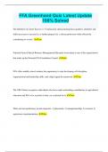
For the spring assembly shown in Figure 1.2, determine the global stiffness
matrix using direct stiffness method, displacement at each node, reactions
at the support, and strain energy in each element.
10 N/mm 20 N/mm 10 N/mm
450 N
1 2 3 4
① ② ③
Figure 1.2. Spring element 6
, Cont.
Using the element stiffness matrix of a spring defined in Eq. (1.3),
u1 u2 u2 u3 u3 u4
10 −10 u1 20 −20 u2 10 −10 u3
k =
(1)
k =
(2)
k =
(3)
−10 10 u
2 −20 20 u
3 −10 10 u4
Using the concept of superposition (direct stiffness method), the global
stiffness matrix is obtained as u1 u2 u3 u4
10 −10 0 0 u1
−10 30 −20 0 u2
K = k (1) + k (2) + k (3) =
0 −20 30 −10 u3
0 0 −10 10 u4
The global stiffness matrix relate global forces to global displacements as
R1x 10 −10 0 0 u1
450 N −10 30 −20 0 u2
= (1.9)
0 0 −20 30 − 10 u
3
R4 x 0
0 −10 10 u4
The homogeneous boundary conditions for the spring system shown in
Figure (1.2) are
u1 = u4 = 0 7
, Cont.
Deleting first and fourth rows of force vector and displacement vector and
the first and fourth rows and columns of global stiffness matrix in Eq. (1.9)
leads to 450 N 30 −20 u2
= (1.10)
0 −20 30 u
3
Solving Eq. (1.10) leads to global nodal displacements at node 2 and 3 as
u2 = 27 mm and u3 = 18 mm
The reaction forces are obtained by substituting the nodal displacements
into the global equations defined in Eq. (1.9) and multiplying the matrices
as u 0
1
R1x 10 −10 0 0 u2 10 −10 0 0 N 27 −270
= = mm = N
R
4x 0 0 −10 10 u
3 0 0 −10 10 mm 18
−180
u 0
4
Strain energies in each element are
U = k ( u2 − u1 ) = 3.645 Nm
(1) 1 (1) 2
2
U (2) = k (2) ( u3 − u2 ) = 0.81 Nm and U (3) = k (3) ( u4 − u3 ) = 1.62 Nm
1 2 1 2
2 2 8
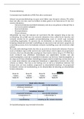
, Example 02
For the spring assembly shown in Figure 1.3, determine the
a) Global stiffness matrix using direct stiffness method
b) Nodal displacement
c) Reactions at the support
d) Forces in each element
e) Strain energy in each element
N
200
mm
N N
100 300
mm ② mm
1 2
3 4
③ 500 N
① ④
N
150
mm
Figure 1.3. Spring element 9
Faculty of Technology
Department of Mechanical Engineering
Finite Element Method for Springs
By
Desu Eshatie
10-Feb-22
,Outlines
❶ Derivation of element stiffness matrix for springs using
❖ Newton’s third law of motion
❖ Principle of minimum potential energy
❷ Examples on springs using direct stiffness method
❖ Example 01
❖ Example 02
❖ Example 03
❸ Examples on springs using principle of minimum potential energy
❖ Example 04
❖ Example 05
2
,❶ Spring element
Consider a spring element shown in Figure 1.1,
k
f1x 1 2 f2 x
u1 u2 x
①
Figure 1.1. One spring element
From Figure 1.1;
➢ Element number: ① ➢ Nodal displacements: u1 and u2
➢ Nodes: 1 and 2 ➢ Stiffness of the spring: k
➢ Nodal forces: f1x and f2 x
The equilibrium of forces at each node i.e. applying newton’s third law
of motion into Figure 1.1 leads to
(1) ① f2(1)
f1x
1 1 2 2 x
k ( u1 − u2 ) k k ( u2 − u1 ) 3
, Cont.
The equilibrium equations at node 1 and 2 are
f1(1)
x
= k ( u1 − u2 )
(1)
f2 x = k ( u2 − u1 )
(1.1)
Eq. (1.1) can be written in matrix form as
f1(1)
x
k − k u1
(1) = (1.2)
f2 x − k k u2
From Eq. (1.2), the element stiffness matrix for a spring element is
k −k
K = (1.3)
− k k
The element stiffness matrix for a spring element defined in Eq. (1.3) can
also be obtained by using principles of minimum potential energy. This
principle states that ‘’of all the geometrically possible shapes that a body
can assume, the true one corresponding to the satisfaction of stable
equilibrium of the body is identified by a minimum value of the total
potential energy’’.
4
, Cont.
The total potential energy ( P ) is given by
P = U + (1.4)
Where;
✓ U - The internal strain energy which is the capacity of internal forces
or stresses to do work through deformations (strains) in the structure.
It is the area under the force-deformation curve.
✓ - The capacity of forces such as body forces, surface traction forces,
and applied nodal forces to do work through deformation of the
structure. Work done by this forces are negative. i.e. the potential
energy of external force is lost.
For a spring element shown in Figure 1.1, total potential energy becomes
P = k ( u2 − u1 ) − f1xu1 − f2 xu2
1 2
(1.5)
2
Minimization of Eq. (1.5) with respect to each nodal displacement is
obtained by taking partial derivatives of the total potential energy as
P P
= − k ( u2 − u1 ) − f1x = 0, and = k ( u2 − u1 ) − f2 x = 0 (1.6)
u1 u2
5
, Cont.
Eq. (1.6) can be written in matrix form as
f1x k − k u1
= (1.7)
f
2x − k k u2
From Eq. (1.7), the element stiffness matrix for a spring element is
k −k
K = (1.8)
− k k
Eq. (1.8) is similar to the element stiffness matrix defined in Eq. (1.3).
Example 01
For the spring assembly shown in Figure 1.2, determine the global stiffness
matrix using direct stiffness method, displacement at each node, reactions
at the support, and strain energy in each element.
10 N/mm 20 N/mm 10 N/mm
450 N
1 2 3 4
① ② ③
Figure 1.2. Spring element 6
, Cont.
Using the element stiffness matrix of a spring defined in Eq. (1.3),
u1 u2 u2 u3 u3 u4
10 −10 u1 20 −20 u2 10 −10 u3
k =
(1)
k =
(2)
k =
(3)
−10 10 u
2 −20 20 u
3 −10 10 u4
Using the concept of superposition (direct stiffness method), the global
stiffness matrix is obtained as u1 u2 u3 u4
10 −10 0 0 u1
−10 30 −20 0 u2
K = k (1) + k (2) + k (3) =
0 −20 30 −10 u3
0 0 −10 10 u4
The global stiffness matrix relate global forces to global displacements as
R1x 10 −10 0 0 u1
450 N −10 30 −20 0 u2
= (1.9)
0 0 −20 30 − 10 u
3
R4 x 0
0 −10 10 u4
The homogeneous boundary conditions for the spring system shown in
Figure (1.2) are
u1 = u4 = 0 7
, Cont.
Deleting first and fourth rows of force vector and displacement vector and
the first and fourth rows and columns of global stiffness matrix in Eq. (1.9)
leads to 450 N 30 −20 u2
= (1.10)
0 −20 30 u
3
Solving Eq. (1.10) leads to global nodal displacements at node 2 and 3 as
u2 = 27 mm and u3 = 18 mm
The reaction forces are obtained by substituting the nodal displacements
into the global equations defined in Eq. (1.9) and multiplying the matrices
as u 0
1
R1x 10 −10 0 0 u2 10 −10 0 0 N 27 −270
= = mm = N
R
4x 0 0 −10 10 u
3 0 0 −10 10 mm 18
−180
u 0
4
Strain energies in each element are
U = k ( u2 − u1 ) = 3.645 Nm
(1) 1 (1) 2
2
U (2) = k (2) ( u3 − u2 ) = 0.81 Nm and U (3) = k (3) ( u4 − u3 ) = 1.62 Nm
1 2 1 2
2 2 8
, Example 02
For the spring assembly shown in Figure 1.3, determine the
a) Global stiffness matrix using direct stiffness method
b) Nodal displacement
c) Reactions at the support
d) Forces in each element
e) Strain energy in each element
N
200
mm
N N
100 300
mm ② mm
1 2
3 4
③ 500 N
① ④
N
150
mm
Figure 1.3. Spring element 9